This thread has been locked.

If you have a related question, please click the "Ask a related question" button in the top right corner. The newly created question will be automatically linked to this question.

LMC7101Q-Q1: Part is getting damage overtime of period

Part Number: LMC7101Q-Q1
Other Parts Discussed in Thread: LMC7101

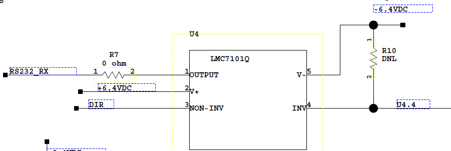
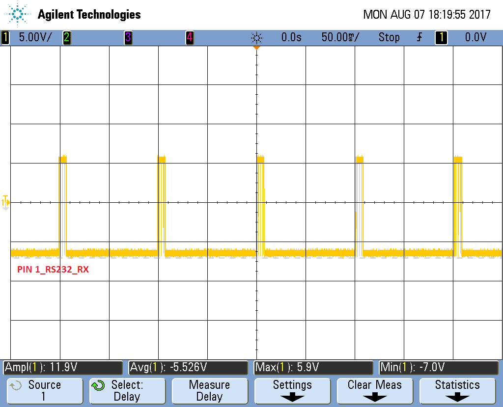
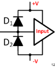
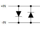
What could possibly happen if my V+ and V- is not there (0 V), but some amount of signal is going through INV and NON-INV pins? Would this damage the IC? Will I be exceeding limit of input pins (V+) +0.3, (V-) - 0.3V?

  • Hello Maulik,

    There are ESD structures (diodes) that protect the inputs and output pins of the device. If you forward bias these structures and your input signal has sufficient current (+/-5mA for input and +/-35mA for output as shown in absolute maximum ratings table) you could damage the device.

    For more information, please take a look at the videos on EOS (electrical overstress) at www.ti.com/precisionlabs
  • We had a unit where LMC7101 failed. V+ and Output pin was shorted. So we are trying to find what could cause it. I test it here in the lab. I do see about 8C to 10C temperature rise on LMC7101 when my V+ and V- is not there (0 V), but some amount of signal is going through INV and NON-INV pins. Having said that, do you think ESD diodes are getting conducted and creating extra amount of heat during this scenario of not having V+ and V-? Which could lead to damaging LMC7101 in over period of time?

    -Maulik
  • Hello Maulik,

    It is difficult to fully understand what is going on here without some additional information. So, can you please provide a schematic and measurements of what you're observing? Here are some questions...please provide any additional information that you think may be helpful.

    1) What is the impedance as seen by the supply pins? In other words, 0V sometimes means that you're connected to ground (low impedance). Sometimes the supply is driven by a power supply...therefore the impedance would be whatever the power supply output impedance is when 'off'. Finally, sometimes '0V' is interpreted and a complete disconnection from all circuitry...therefore it would be considered high impedance and there would be no current flow through the supply pins.
    2) What is the load?
    3) Given a 10C change in temperature, this equates to dissipating approximately 80mW of power. How does this compare to the load?
    4) Please quantify "...some amount of signal going through the INV and NON-INV pins." Are you referring to current or voltage? Ideally the inputs of a properly powered amplifier have equal voltages. Are they being pulled apart somehow? If you can measure the current flowing into the input(s), how does it compare to the current flowing out of the output? If the supplies are high impedance the current flowing out of the device should be approximately equal to the current flowing into the device. Note that the input bias current of the device is just 1000pA (max).
    5) What is driving the input(s)? What is the impedance as seen by the inputs of the device? What is the voltage at the input(s) and current capability of the signal source?

    Thanks!
  • Hi Pete,

    See below screenshot of LMC7101 from our schematic. Basically in this application, we are controlling and monitoring data lines of customer's application. Our device provide power such as 6.4V and -6.4V.

    During normal operation, we have PIN1 which is a RS232 Receive line, which goes to our processor. Pin 2 is +6.4VDC. Pin 3 is one of Data line. Pin 4 is also 2nd data line. Pin 5 is -6.4VDC.


    Now, during scenario of not having any power but data lines are still active, I see measure following:

    Pin 1: 0V

    Pin 2: 0V

    Pin 3: 1.1V

    Pin 4: 0V

    Pin 5: 0V

    Impedance across V+ and V- is 471kOhms when there is no power (0V). 

    During no power scenario I see LMC7101 get little heat up.

    -Maulik

  • Hello Maulik,

    For clarification:

    When you say Pin 2 and 5 are 0V:

    a) Do you mean the pins are connected straight to ground? 

    b) Are they connected to a power supply unit which are both set to 0V?

    c) Are they floating? (Connected to nothing)

    Also, when you say "Impedance across V+ and V- is 471kOhms when there is no power (0V)."

    Are you saying the resistance from V+ to V- is 471k ohms? 

    If so, we would like to know the effective series resistance of your power supply unit and/or any resistance from V+/V- to ground. 


    Thanks,

    -Bobby

  • Hi Bobby,

    When I say PIN 2 and PIN 5 are 0V, means there is no power to our board. When there is a power, PIN 2 has 6.4V and PIN 5 has -6.4V. When there is no power,  I can say voltage is 0V (It's not connected to ground).

    Yes resistance across V+ and V- is 471kOhms. Resistance acorss my power supply is about 450kOhms.

    My concern is  if V+ and V- is not there (0 V, power is off to board, not connected to ground), but some amount of signal is going through INV and NON-INV pins? Would this damage the IC?

    -Maulik

  • Hey Maulik,

    There are back to back diodes on the inputs as well as diodes from the input to the supply pins as shown below.  It is of utmost importance to ensure that the current flowing through these pins does not exceed the absolute recommended operating conditions as listed in Table 6.1 of the data sheet.  Here is an idea of what the diodes look like.
       
    An input differential voltage of 1.1V will forward bias one of the input diodes and it will therefore conduct current.  This violates the datasheet common mode input voltage range requirement of +/- 0.3mV from the supply pins and is not recommended by TI.

    In order to protect the device you must limit the current that flows into/out of the pins of the device.  Placing a resistor in series with the input pins will limit the current.  You can size the resistor based on your worst-case analysis including the largest expected input voltages and the min/max currents given in Table 6.1.   It is recommended to include design margin, so you should consider limiting the current to half of the value given in the table. 
    In addition, you should add TVS diodes across the power supplies and, depending on the load, consider adding protection for the output pin as well.  For further information please watch the following series of videos on EOS.  The first 2 videos discuss the need for the diodes and input resistor(s).  The third video discusses how to select them.


    www.ti.com/precisionlabs

    -Bobby