This thread has been locked.

If you have a related question, please click the "Ask a related question" button in the top right corner. The newly created question will be automatically linked to this question.

TINA/Spice/LMP8601: In the sample circuit below, why does the out voltage start from 2V?

Part Number: LMP8601
Other Parts Discussed in Thread: TINA-TI,

Tool/software: TINA-TI or Spice Models

Thank you for your patronage. 

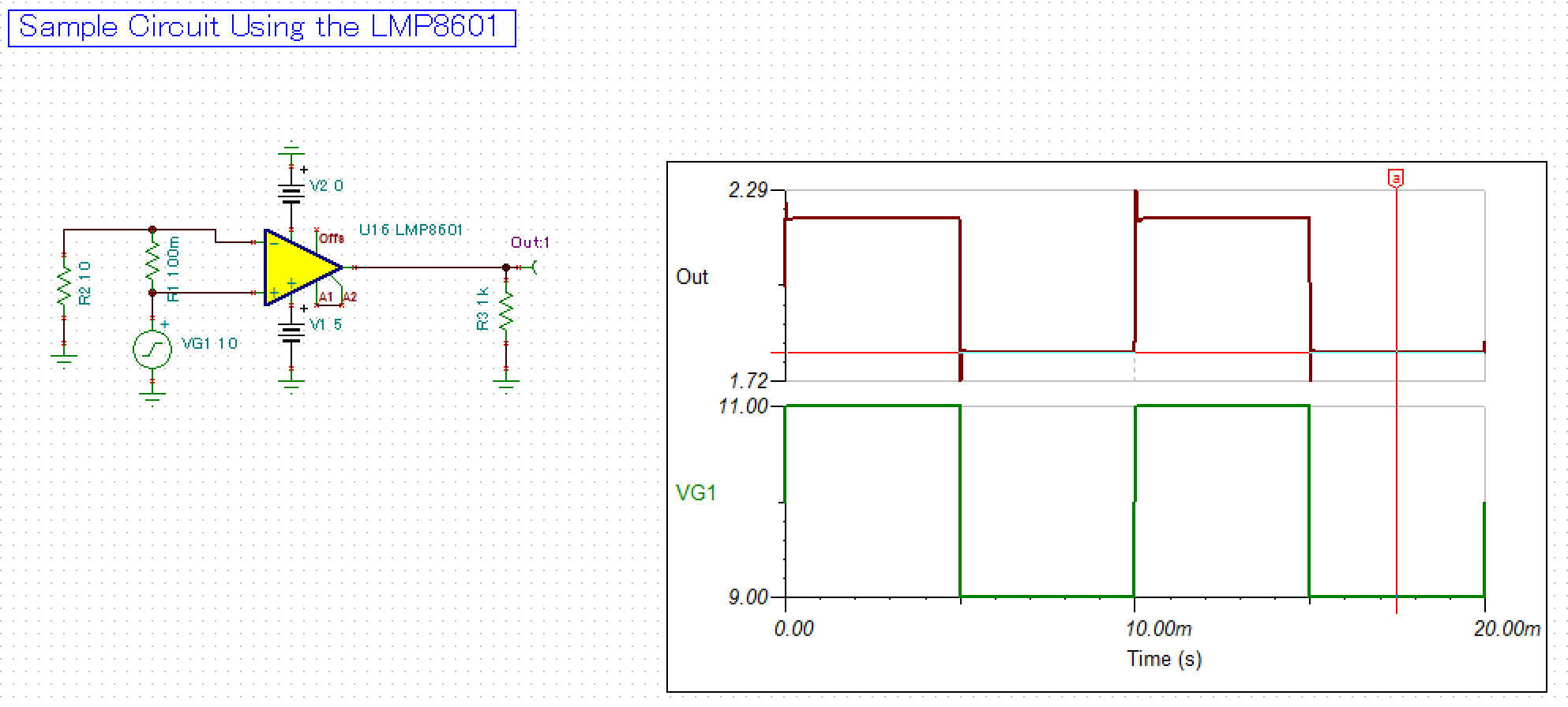
In the sample circuit below, why does the out voltage start from 2V? I think that it starts from 0 V because nothing is connected to the Offset pin.

  • Hello,
    I believe if you look at the signal generator VG1, and click on the [...] that defines the type of waveform by what I'm fairly sure is currently "Square Wave," you can see what kind of signals are available to generate and what they look like. I also think that this is just how TINA models square waves. If you only need a little bit of signal, you can define your signals piece by piece in another one of the waveform options.

    Also, try playing with the "use initial conditions" option when you run the transient. That may also be the issue, but I can't say for sure. Hope this helps.
  • I'm sorry for late my reply, and thank you for your reply. Because of my little knowledge, even taking into account your hints, I can't understand why out voltage start from 2V, not 0V.

  • Hi JapaneseStudent,

    Thanks for using TI E2E! We will try to help you out. Can you please send us your simulation? You can attach it in your reply. 

    I am curious where you find that LMP8601 model as we do not have any available in our website. Did you exported it from the PSPICE?

    Regards,

  • JapaneseStudent,

    Your output starts at 2V because your input starts at 1A (VG1 = 10V, R2 = 10 Ohm, 10V/10ohm = 1A). 1A x 100mOhm x 20V/V = 2V. It goes up to 1.1A and then back down to 0.9A after that, but the simulation starts with VG1 = 10V.
  • Dear Ms. Mayrim Verdejo,
    Thank you for your reply. I solved this problem by Mr. Jason Bridgmon 's answer.
    I did not know that I could send a simulation circuit. I will send a simulation circuit from now.
    I got LMP8601 sample circuit from C:\Program Files (x86)\DesignSoft\Tina 9 - TI\EXAMPLES\NSC Test Circuits\LMP8601 Test Circuit.TSC
    Thank you for your kindness.

  • Dear Mr. Jason Bridgmon,
    Thanks to you, I solved this problem. I am very grateful to you.
    I was misunderstanding that since the offset pins are not connected, the voltage starts from 0 V.
    I am very saved because there are no people around me who are familiar with such things. Now I can design the circuit using the LMP 8601.
    Thanks a million.

    I made a mistake and made my reply "This resolved my issue".