This thread has been locked.

If you have a related question, please click the "Ask a related question" button in the top right corner. The newly created question will be automatically linked to this question.

INA226: Positive and negative voltages with common grounds

Part Number: INA226
Other Parts Discussed in Thread: TIDA-00313

Relating to the thread https://e2e.ti.com/support/amplifiers/current-shunt-monitors/f/931/t/426430 I have a question to the circuit below:

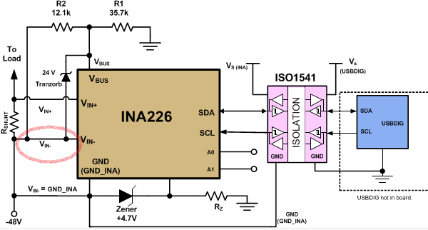
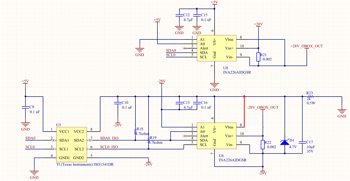
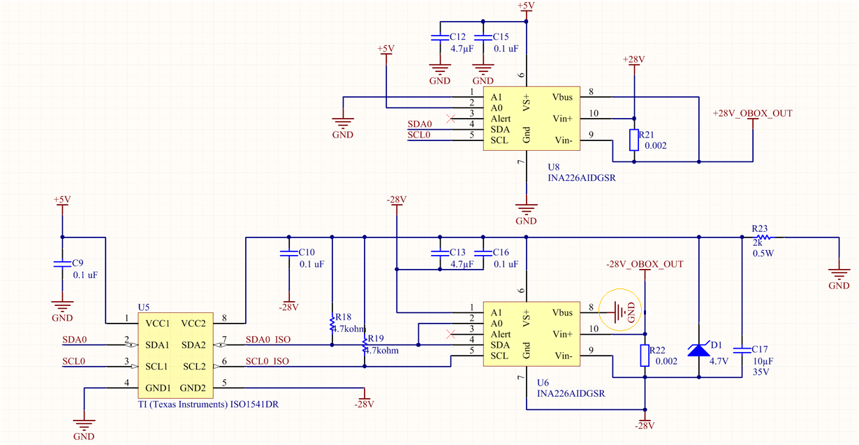
Should not input Vbus of Chip INA226/U6 be connected to circuit-GND to measure the negative voltage? According the INA226 datasheet Vbus is referenced to GND-pin of INA226 (in this case -28V). I think in this circuit Vbus sees only the Shunt-voltage (R22).

  • Hi Ewald,

    You are correct. It should be connected to GND_INA. That is a mistake on the TI design drawing and customer replicated it. Actually, we are currently fixing the TI design document this month. 

    The connections should look like this:

  • Hi Mayrim,

    you are showing the example TIDA-00313 (-48V Telecom Current/Voltage/Power Sense with Isolation). In this case, I think the originally shown circuit (at https://www.ti.com/lit/ug/tidu361/tidu361.pdf ) was right, because you are measuring Vin+ at load-side (this is what user wants to know) and Vbus is referenced to GND (I mean GND at R1) via a voltagedivider. You changed the circuit to measure at -48V source-side.

    Anyway voltage at load-side can be calculated (R_SHUNT and current is known) and the advantage of measuring at source-side (Vin-) is to measure current without the current which flows across R1, R2 and INA226-internal R_Vbus (830k).

    Back to the example of Mrs. Rabab (e2e.ti.com/.../426430):

    I would change the circuit like this:

     .

    Only disadvantage of this circuit is to measure Vbus at -28V source-side (because this is U6-GND) and not at load-side (-28V_OBOX_OUT). If you want to know voltage at load-side you must calculate -Vbus + R22 * I_load in software. In this case and under assumption of 1A current: -28V + 0.002R * 1A = -27.998V.

    Advantage is, like mentioned above, you do not measure the current which flows through INA226-internal R_Vbus (830k). This is 0.00337mA at 28V.

    Is this correct?

    I am looking forward to realise a circuit similar to Mrs. Rabab's circuit. I think +/-15V power-supplies are very common and this is simple a way to monitor this such power-sypplies. Maybe you pick up this circuit (if it is correct) to your _datasheets

    Best regards,

    Ewald

    Current/Power Monitor

  • Hi Mayrim,

    I've seen my ciruit-modification is wrong. U6 Vbus shoud be connected to GND!

    Kind regards,

    Ewald

  • Hi Ewald,

    I am sorry I mixed replies with TI design issue and Rabab's circuit. 

    1. Yes! In your circuit the Vbus should be connected to GND, not the negative rail. Your last circuit is correct (Unfortunately, Rabab missed that bad connection in the other post). 

    2. For the TI design topic. I am the designer of this TI design. I agree with you, the original circuit was right as my intend was to measure the power at the load and not the source-side. The reason we are changing the connections is because we realized that all my calculations in the document were done at the "source-side". So my colleagues are changing the drawing to match the calculations and will add a note explaining the differences of the connections. Thanks for the feedback!!

    Please let us know how your system/application works out! That's a great example for customers. As you mentioned, we could use it for some reference design or app note!

    Thanks for using TI E2E forums!

    Regards

  • Hi Mayrim,

    I have a further question:
    I want to connect the Alert Pin of INA226. The INA226 at negetive Power-Supply is referenced to -15V in my case. I want to bring the Alert Output to my 2.5V digital System. Is the Alert Open-Drain-Output of INA226 capable to withstand a Drain-Source Voltage of 17.5V (15V + 2.5V)?
    How high is the maximum Drain-Source Voltage of the Alert Open-Drain-Output Transistor?

    Kind Regards,
    Ewald
  • Hi Ewald,

    Yes, but you will need to limit the current. I would recommend a pull up resistor greater than 10k ohms.

  • Hi Mayrim,

    are you sure?

    The yellow tagged Alert V_OL value says the max. voltage, when the Open-Drain Output pulls-down respectively the transistor is connected through and when a current I_OL = 3mA is flowing through the transistor.

    I want to know the maximum pull-up voltage (when the transistor is switched off). This value is missing in the datasheet. At section 6.1 "Absolute Maximum Ratings" I find the I_OUT (Open-drain digital output current) = 10mA max. and the V_VS (Supply voltage) = 6V max. only. I cannot find any statements relating to the maximum pull-up voltage of ALERT Open-Drain-Output.

    For me it is quite clear to limit the current below 10mA max. which is flowing through the alert transistor. I have to adjust the pull-up resistor accordingly.

    Kind regards,

    Ewald

  • Hi Ewald,

    I assumed we had a transistor with high voltage but I was wrong. We reviewed the INA226 design and the ALERT output transistor is 5V NMOS, it can't handle more than 6V. You will need to isolate it as well.

    I requested this info to be included in datasheet revision. Once again, I am sorry for the confusion.

  • Hi Mayrim,

    thank you for your prompt answers to my questions! I think all my issues are solved now.

    Kind regards,
    Ewald