Because of the Thanksgiving holiday in the U.S., TI E2E™ design support forum responses may be delayed from November 25 through December 2. Thank you for your patience.

This thread has been locked.

If you have a related question, please click the "Ask a related question" button in the top right corner. The newly created question will be automatically linked to this question.

TLV8801: Compatibility with tps61098x and output series resistance

Part Number: TLV8801
Other Parts Discussed in Thread: TLV8802, TPS706

Greetings,

I'm working on a design which involves using TLV8801 or TLV8802 as a signal conditioning circuit for a PIR sensor. For both PIR sensor and TLV880x OPAMPs noise is an issue. The power source is a TPS61095 boost regulator in low power mode. As mentioned in the datasheet of TLV880x "Low bandwidth nanopower devices do not have good high frequency (> 1 kHz) AC PSRR rejection against high- frequency switching supplies and other 1 kHz and above noise sources, so extra supply filtering is recommended if kilohertz or above noise is expected on the power supply lines." What sort of filtering is needed to power PIR and the OPAMP from this regulator?

Also the output of the OPAMP is sampled by an ADC whose sampling capacitance is 2.5 pF. What sort of series resistance is needed for driving such a capacitive load?

Thanks and regards,

Prithvi

  • Hello Prithi,

    Adding a R-C filter in series with the supply line will help. Since the quiescent current is so small (<1uA), a fairly substantial RC filter can be created with reasonable RC values.

    Also, The PIR sensor itself (if it is powered) does not have a lot of power supply rejection as they generally use a FET buffer (similar to an electret mic). The PIR supply needs to be clean to the sensor, too.

    You could add a 10k series resistor to the supply and only drop 10mV. Add a 4.7uF cap, which will give you at least 40dB rejection at 1kHz. Keep in mind that this assumes light loads. If you have to increase to 1k, then the cap needs to increase to 47uF.

    You may want to concider placing the PIR sensor and amp on a dedicated linear (LDO) regulator for increased supply rejection and regulation.

    For driving the ADC, the series output resistor needs to be at least 50k, and you probably want to add an external charge reservoir cap of at least 100pF to ground across the ADC input.
  • Thanks a lot. What kind of PSRR should I be looking for in a LDO?
  • Hello Prithi,

    You want to pick a regulator with as much (ripple) rejection as possible in the frequency range of the switchers switching frequency. Unfortunately, micropower LDO's will suffer the same PSRR issues as micro power amplifiers. "Ripple Rejection" = PSRR for regulators.

    Our lowest power LDO is the TPS78xx series (500nA Iq). If you look at the "Ripple Rejection" graph, it provides native rejection up to about 100Hz, then improves after 10kHz, mostly due to the 2.2uF output capacitor.

    Usually, good low ESR capacitors (usually ceramic), with proper layout and grounding, should be able to suppress most of these higher (>10khz) frequencies .

    The simple RC line filter is the easiest to implement, but the LDO may be needed if the amplifiers load current causes problems with the supply voltage drop across the RC filter.
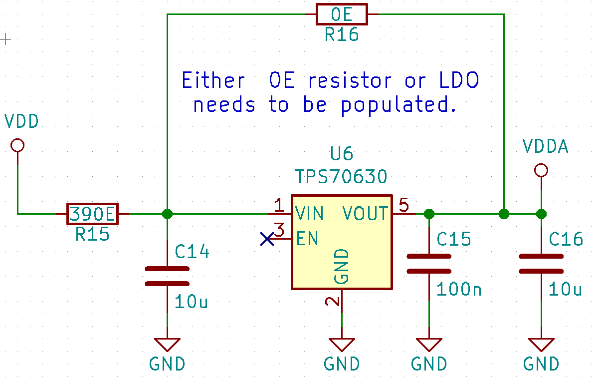
  • Thanks Paul. I'll try with the TPS706 based LDO which has better ripple rejection but with 1 uA Iq.

  • Hello Prithi,

    Looks good. Just be sure to observe the Input and Output capacitor recommendation in the TPS70630 apps section (8.1.1) so that the regulator is stable. The PIR sensor should be fed from the most stable supply to prevent feedback,