This thread has been locked.

If you have a related question, please click the "Ask a related question" button in the top right corner. The newly created question will be automatically linked to this question.

INA250: Mesuring motor current with INA250 amplifier

Part Number: INA250
Other Parts Discussed in Thread: INA210, INA302, INA240, INA180, INA212, INA139, LMP8645, INA282, INA270

Good Morning,

I want to mesure 2 types of  motor current 

Nominal current : 10A

Standby current : 50mA

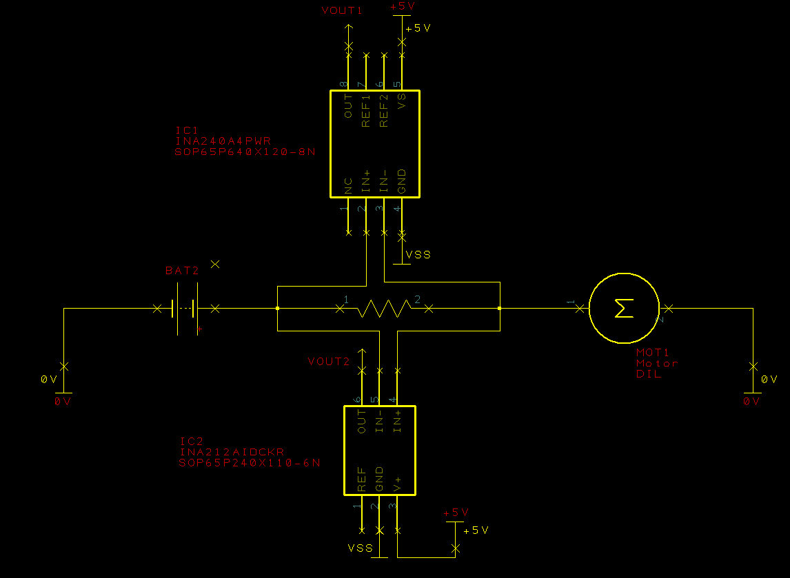
I choose the INA250 current sensing amplifier to mesure these 2 current. 

is it possible to mesure 50mA current with this circuit ?

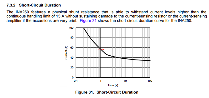
The peak starting current of my motor is around 55A, did the INA250 amplifier support this peak of current? 

Thank you!

  • Hello Achref,


    I will look into the 50mA operation, but I would overall not recommend using the INA250 with 55A peak load currents for the following reasons:


    1. We cannot guarantee our specifications for 55A loads currents because we specify the absolute max load current to be +-15A.

    2. The applications plot (Figure 31 of datasheet) is not a spec or behavior we can guarantee and is also run from room temperature (25C). If the part is already heated up from running a 15A load current, then the 1 second duration for 55A will be reduced. Additionally, the 1 second duration will also be diminished if this 55A peak repeats itself within a short duration of time and the part has not had a chance to cool down from the heat generated by the first peak.


    3. Running load currents above the abs max can affect the tolerance of the internal shunt resistor. We specify this similarly to other shunt resistors in our datasheet electrical characteristics table as seen below. So you also run the risk of changing the shunt resistance over time.


    ----


    Are you considering using a PWM with this as in-line? This is also not recommended and you can about this here:


    You can consider the INA240 and an external shunt as an in-line configuration, if you are ok with increasing board space. The INA210, INA302, and INA180 are also options for low-side configurations.


    Here is some more links for more info in the meantime while I work on more specific recommendations.

    www.ti.com/.../TIDA-00171 current feedback&tisearch=Search-EN-Everything


    Peter Iliya

    Current Sense Applications

  • Also, be aware that if you want to measure 50mA of current with the INA250, you could only use either A3 or A4 gain variants of INA250 and that your voltage supply would need to be at least >= 8V or >=20V respectively. This can be determined by using the Ios (input offset current), which is how we represent Vos (input offset voltage) of the part. The following analysis shows that for measuring 50mA with INA250, you will have ~50% error immediately (not accounting for CMRR, PSRR, shunt tolerance, gain error, and noise).

    INA250A3:

    • Ios_max = +-30mA
    • Gain = 0.8V/A
    • Vout = (IL +- Ios_max) *Gain
    • For IL = 50mA, Vout = 40mV +- 24mV
    • For IL = 10A, Vout = 8V +- 24mV

    INA250A4:

    • Ios_max = +-20mA
    • Gain = 2V/A
    • Vout = (IL +- Ios_max) *Gain
    • For IL = 50mA, Vout = 100mV +- 40mV
    • For IL = 10A, Vout = 20V +- 40mV

    Peter Iliya

    Current Sense Applications

  • Hello Peter,

    Thank you for your very helpful reply.

    Yes, is it possible for me to use an external shunt resistor.

    is it possible to mesure the operating current 10A, the standby current 50mA and the peak starting current 55A with the INA240 current sensing amplifier?

    Could you help me please to choose an external shunt resistor able to support all these current?

    Thank you! have a nice day!
  • Achref,

    Using one INA240 in the in-line application to measure all three of these currents will be impossible. If you just wanted to measure current from 50mA to 10A, your best option would be to choose a shunt resistor of 4.9mOhm and the INA240A3 (gain = 100V/V) with the device referenced to ground. This would give you an output voltage range of 24.5mV - 4.9V for 50mA - 10A of continuous current.

    This is risky because the recommended power supply if 5V for the INA240 and with your nominal 10A driving the Vout so close to your power rail, every time the PWM voltage signal driving the motor jumps, the Vcm of the INA device also jumps. While the INA240 has good rejection of these Vcm transients, there still will be a resulting transient on the Vout which will saturate your INA240 output since is already so close at 4.9V. Once the Vout saturates, the output stage of the part is not in it linear mode of operation and we cannot guarantee our specs anymore during this mode of operation. This is why we suggest referencing the part to 2.5V. You could try testing this configuration in your system and see it if the Vout saturates or not, but considering all of the other sources of drift and error, this won't be a robust solution. You can read about this PWM rejection in in-line motor sense application here:

    www.ti.com/.../sboa172.pdf

    If measuring the 50mA of current is absolutely required, you might want to consider using two current sense amplifiers with one in the low-side or high-side that is only there to measure 50mA.

    Peter Iliya
    Current Sense Applications

  • Good morning peter,

    Thank you very much for your reply.

    Mesuring the both current 50mA and 10A are absolutely required in my application.
    You are right, i think the optimal solution is to provide 2 circuits one to mesure the 10A and the other to mesure the 50mA.
    ...
    I well checked all your datasheets, but i have never find the input current range of each circuit, so it's difficult to choose the optimal circuit for my application.

    1 --- Could you help me please, which circuit i provide for mesuring 10A and which circuit for mesuring 50mA?

    Just for information, i am using a DC brushless motor with an operating current arround 10A.


    2 --- a last question please, do you thing that is it possible to use the same shunt resistor for the both circuit ?

    Thank you, have a nice day.
  • Achref,

    How are you driving this motor? What exactly do you mean by standby current? Are you using pulse-width modulated signals to drive the motor, if so, what is the frequency of the signal? Are you using these measurements for failure mode detection or for speed control? What are your available power supplies for the amplifiers.

    You could consider one high-side shunt resistor (22.5mOhm) and two amplifiers of differing gain measuring the same differential voltage across the same shunt resistor. If you have INA240 (with gain of 20V/V) and the INA212 (gain of 1000V/V) and power them with 5V and reference them to ground, then the Vout for the INA240 at ILOAD = 10A would be 4.5V and the Vout for INA212 at ILOAD = 50mA would be 1.125V.

    Peter Iliya
    Current Sense Applications
  • Hello Peter,

    Thank you for your early reply.

    Motor is powered with a fixed power supply of 27V ,  drived with pulse width modulated signals .  for information, it's a compact system, motor + drinving electronic board. i could only change with an extern applicartion the duty cycle of the PWM, (PWM 0% --> motor stop), (PWM 100% --> motor running) and it's not possible to put my shunt resistor on the H-Bridge. 

    in my application, i'am interrested in the absorbed current off all the system when motor is running and when it is stop.  When motor is running, it consume 10A (this is the nominal current). When motor is at stop ( PWM duty cycle at zero), it consume  between 10mA - 50mA, this is the standby current.

    i want  mesure the absorbed current of all the compact system (motor + its  driving electronic board) in both modes of operation.

    all these measurements are done for failure mode detection.

    Concerning power supplies of amplifiers, i haven't any constraint. i 'am free i will choose the optimal power supply.

    What do you think about my electronic circuit?  i want  know if the  2 amplifiers INA240 and INA212 could support the starting current (55A), for information, i would not mesure the starting current, i want only mesure the nominal current 10A and the standby current 50mA.

  • Achref,

    With a 27V common-mode the INA212 will not work since its maximum Vcm is 26V. There are three alternative parts that meet the Vcm>27V and have a gain of 1000x: INA139, INA282, and LMP8645. The INA139 and LMP8645 have adjustable gains, but their input offset voltages are 1mV, which will not work because you are trying to sense something in the 100's of uV.The INA282 has a Vos_max of +-70uV so this works well enough. In your schematic you also have the reference pin floating. You will need to connect these to ground or mid-supply. In my following alternatives solutions you can reference both parts to ground.

    Note: I am not sure how much you will vary the speed (duty cycle), but if your system requires it to be something other and 100% or 0%, then it will be important to know and could change my recommendations. I'll assume power to both parts come from 5V rail.

    Soluion 0:
    - This is your current schematic except replace INA212 with INA282.
    - Rshunt = 22.5 mOhm.
    - Reference INA282 to ground or mid-supply.
    - Reference INA240 to ground.

    Solution 1:
    - Similar to Solution 0, but use Rshunt = 32 mOhms.
    - Use the INA282 (gain 1000V/V) to sense 10mA to 50mA --> yields Vout = {320mV - 1.6V}.
    - Reference INA282 to ground or mid-supply.
    - Use the INA270 (gain of 14V/V) to sense 10A current --> yields Vout = 4.48V.
    - Reference INA270 to ground.

    Solution 2
    - Similar to Solution 0, but use Rshunt = 50 mOhms.
    - Use the INA282 (gain 1000V/V) to sense 10mA to 50mA --> yields Vout = {500mV - 2.5V}.
    - Use the INA139 (gain of 1000uA/V) to sense 10A current. This is a current output device and if powered with 5V supply, Vout_max = 5V - 0.7 - Vdiff = 5V - 1.2V = 3.8V. Use a load resistor (RL = 7.6 kOhm) to convert Iout to Vout.
    - Thus for ILOAD = 10A, Vout_INA139 = 10A * 50 mOhms * 1000uA/V * 7.6 kOhms = 3.8V.
    - Reference both parts to ground.

    ---------

    In terms of withstanding the 55A peak at start-up all you need to do is to make sure that Rshunt*55A > Absolute Max Differential input of the device and this looks to hold true for all of the possible devices listed.

    Peter Iliya
    Current Sense Applications
  • Hello Peter,

    Thank you, I think this revolved my issue, i will test the three solutions, i will keep you informed.

    Thank you!