This thread has been locked.

If you have a related question, please click the "Ask a related question" button in the top right corner. The newly created question will be automatically linked to this question.

OPA2170: Open loop output resistance

Part Number: OPA2170
Other Parts Discussed in Thread: TINA-TI

Hi,

Please tell me the characteristics of OPA2170AIDR.

Question: Please let me know if you know the minimum and maximum values of Open-loop output resistance Ro.
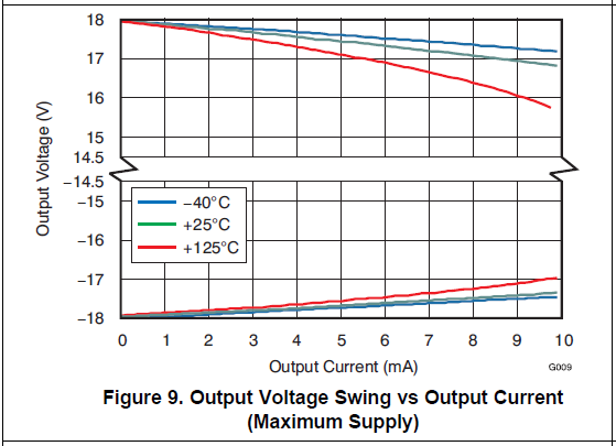
                Operating conditions are f=0Hz and Io=0 to 5mA.

Data sheet As seen in Figure22, we think that Z0=50Ω
I want to know the range.
Is there a manufacturer's warranty?

best regards

  • Cafain,

    Since you're asking about 0Hz, I think you're likely more interested in the closed-loop saturated output resistance which will determine how close the output can swing to the rail.  There are a few guaranteed output swing vs. output current specifications in the datasheet which I've copied below.  While sourcing/sinking 1mA the output will not be more than 115mV/70mV away from the rail as given in the swing from positive/negative rail specifications.  Also over the full temperature range with a 10k load and a +5V supply the output will be within 30mV from the negative rail and 50mV from the positive rail.  The typical output voltage vs. output current graphs can help you predict typical output swing for the full range of output currents.

    Keep in mind that these specifications are based on a saturated output stage which will result in high levels of non-linearity and reduced open-loop gain.  As given in the final output voltage swing from rail specification in order to have an open-loop gain >110dB the output will need to be at least 350mV away from each rail with a 10k load.

  • Cafain,

    On the other hand, if you are more interested in change in open loop voltage gain at 0mA ,-5mA, and or +5mA . Then I would say the change is meaningless because open loop DC gain is so high. Also current loads are high impedance therefore there won't be any theoretical change in open loop gain at DC. Do these currents represent some resistance loads?
  • Cafian,

    Simulation show 100 ohms at DC. 0mA, -5mA, or +5mA

    ZOUT sbom467a.TSC

  • Hi, Ron-san

    Thank you for the simulation.
    Please tell me how to operate "Open-loop output Impedance vs Frequency" using TINA-TI.

    Is this simulation result "typ"?
    Is it possible to get "min" and "max" in simulation, for example?

    best regards
    cafain

  • Hi Cafain,

    You can find a good description of how to simulate these parameters in this blog post:
    e2e.ti.com/.../spice-op-amp-macromodels-trust-but-verify

    The simulation results will show the typical parameters and are not capable of showing min or max as those values depend on process variation for each device.

    Hope that helps,
    Paul
  • Cafain,

    This is how.

    Gain defaults to a dB scale. ZOUT = 10^ ([left side flat gain]/20)

    You may also right click gain scale and change to linear scale which also shows the maximum value (100.015ohms)

    I do not have a range, but I use you that the variation in Aol  (110dB min, 130dB typical, estimated 150dB max) is +/-20dB will have a bigger effect on the required input change to support 0mA and 5mA.

    5mA change across ZOUT of 100 ohms is 5mA * 100 ohms = 0.5V.

    If AVD is 110db, input change is 0.5V/110dB = 1580nV

    If AVD is 130db, input change is 0.5V/110dB = 158nV

    If AVD is 150db, input change is 0.5V/110dB = 15.8nV

    At this point is this, give the customer the result from Collin's and my efforts.