This thread has been locked.

If you have a related question, please click the "Ask a related question" button in the top right corner. The newly created question will be automatically linked to this question.

TLV2401: Input offset voltage issue

Part Number: TLV2401

Dear sir,

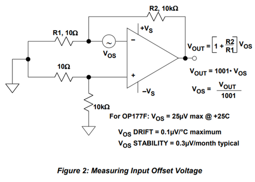
Excuse me. I measured the input offset voltage of TLV2401 on TI EVM board by the topology below. (VCC=5V)

The measured offset voltage of one sample is about 400uV, but the other one is about 1200uV.

I know the input offset voltage spec. in the datasheet is 390uV(TYP) and 1200uV(MAX).

But in the datasheet page8, figure2, the input offset voltage is almost zero when common-mode input voltage=0V.

Why??? Would you please explain the difference?

Thank you very very much.

  • Hi CK,

    We are taking a look at this and will get back to you soon.

    Regards,
    Jas
  • CK
    The typical input offset voltage in the TLV2401 datasheet does not equal the mean value for a large number of samples. In other words, it is not the value in a histogram plot with the largest count. For example, a histogram for input offset voltage for the TLV2401 would have a mean value of nearly 0V, not 390uV. the typical value in the case of input offset voltage is more of an indication that typical parts will be less than that typical value of 390uV. Typical offset indicates that if a random device is selected, the offset will typically be less than or equal to that value and all devices are tested to be less than the maximum value, in this case 1200uV.

    The fact that you measured two devices and found one to have an offset of 400 uV and the other to be be 1200 uV makes me curious how you are making your measurement. From your post, I understand that you are interested in offset voltage with an operating voltage of 5V and a common mode of 0V. It is common to use a two amp loop with significant gain in order to measure input offset voltage. Can you share how you are measuring the offset voltage? In regards to the results you shared, I would not expect you to find a device that was at the maximum of our offset spec. So that is why I am asking about your method for measuring the offset voltage.
    Chuck
  • Dear Chuck,

    I used the below topology on TI EVM board to measure the offset.

    Is it OK?? Thank you very much for your response.

  • CK

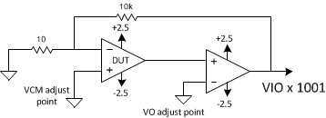
    That is not exactly how we do it.  We use what is called a two-amp loop which provides control of both the output and the input.  The circuit looks like this.

    Theoretically, what you are doing is fine. I am struggling to explain why your readings are so high.  I presume your resistors are measured, known values, and that you are using a precision voltmeter.  Depending on how much noise you are picking up, you may need to average.  I wonder if you are causing the output to oscillate when you connect your meter due to the added capacitive load.  You may want to add 10k in series between the output and the meter and see if that alters your measurement.  this is another reason why we use the two-amp loop.  Our test hardware has many resources connected to the output for various tests and using the 2nd amp allows us to isolate the DUT from these loads.

    Chuck

  • Sorry CK, my image didn't load.  Now with the circuit.