This thread has been locked.

If you have a related question, please click the "Ask a related question" button in the top right corner. The newly created question will be automatically linked to this question.

XTR105: Doesn't work

Part Number: XTR105
Other Parts Discussed in Thread: TINA-TI

XTR105 doesn't work.

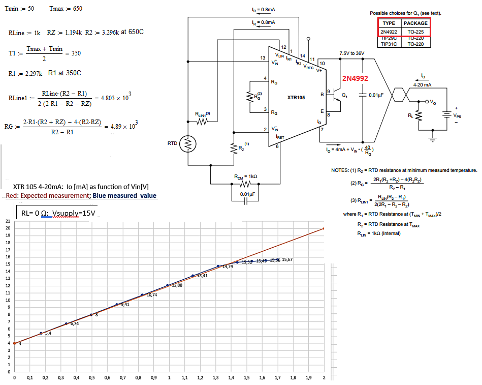
XTR105 has to deliver out 4-20 mA for a PT1000 at  temperature range 50C-650C. I used a decade resistance box instead of PT1000.

1) The applied circuit is that diagram, that is recommended by the Data sheet;Texas Instruments.

2) Vin of the unit has been checked and is Vin=0-2V as datasheet promised.

3) The circuit has been tested  with a RL= 0, 100, 200 Ohms at Vsupply=15V

4) The length of the transmission wire is very short , it is about  5cm.

5) XTR105 startes with 4 mA at Rz=RTD=1.194k Ohms for T_min=50C, but it goes to a saturation state at Vin about 1.3V.

6) Because of saturation the output current=Io can't  reache 20mA at RTD=R2=3.296k Ohms for T_max=650C.

Maybe I did something wrong, but I share you the calculation I have done. I'm waiting for your  suggestions.

  • Hi Farid,
    Could you provide a schematic? That would help us troubleshoot this problem much more accurately.
  • Dear Alex Davis;
    Thanks for your comment; I attached the diagram, that is in the data sheet of XTR105. Please look at this ond gave me some hints.
  • Hi Farid,

    I believe the issue is the common-mode voltage at the inputs to the XTR105 based on your value for Rcm. From the datasheet, you can see that the common-mode input range is 1.25V to 3.5V. So even though your differential input signal is only 2V, you need to keep the average voltage on the pins between 1.25V and 3.5V. I have attached a behavioral simulation for the XTR105 that may help you with the adjustments. This model is purely for understanding XTR functionality and observing dc behavior, it does not model transient behavior or reflect the XTR accuracy.

    XTR105 Limit issue.TSC

  • Hi Zak;
    I'm very excited to read or see the document, but unfortunately I can't open your link.
    Is it possible for you, send it as pdf or as image? You can upload it as image in your text field.
    I'm waiting for the attached file. Again thank you.
    Farid;
  • Hi Farid,

    Sorry, the file I attached was a simulation file for TINA-TI.  If you'd like to simulate this circuit, you can download TINA-TI here:

    Here is an image of the file and two simulations showing the input and common-mode level. Note that this model is not going to show the same behavior as your circuit because the common-mode limitations are not included in the model. But you can see in the datasheet that the upper input common-mode limit is 3.5V. This could shift a bit with process variation so I have shown two simulations showing the input values once the common-mode hits 3.3V and 3.5V. Once this limit is reached, the front end instrumentation amplifier will saturate and you won't be able to increase the output current any further.

    The next question is obviously how do you fix this? My recommendation would be to change Rcm in your circuit to 680 Ohms. This balances the input towards the middle of the common-mode limits and keeps you about 0.5V away from either limit as shown below.

    I hope this helps and please let me know whether or not this fixes your issue!

  • Hi Zak;
    Thank you for your reply and very good documentation. I have solved 4-20 mA with some discrete components. But I'm absolutely sure to use your method  very soon, because XTR105 will make my design easier with few components.
    Again thank you for your help.

    Best regards Farid;