This thread has been locked.

If you have a related question, please click the "Ask a related question" button in the top right corner. The newly created question will be automatically linked to this question.

LM324A: or INA117P: Voltage drop reading at different sections of a cable

Part Number: LM324A
Other Parts Discussed in Thread: TLV4170

Disclaimer: my electronics knowledge is limited.

Goal 1:

See attached figure.  I want to measure the voltage drop at various locations (voltage taps) along a DC power cable. The cable has a 32V drop across it @ 100A. The cable power supply is separate from the op amp power supply (no common grounds).  Basically, I want to use op amps to measure voltage like a multi-meter.  Is it possible to measure these voltage drops/taps using op amps?  What is the circuit?  I have several LM324A and INA117P chips to try.  Are there better chip options for this application?

Goal 2:

Once I can measure the voltage taps, I would like to subtract one voltage tap from another using op amps (e.g. VT2 - VT3) to monitor the differences between the cable sections.  The sections are all the same, so the voltage drop should be similar across each of them, and they should subtract to ~0V.  Is this possible and what is the circuit?

Note: I do not currently have a bipolar supply for the op amps, but am willing to get one if necessary, or try the virtual ground technique. I am currently using a 15V single supply for the op amps. Right now, I am simulating the large power cable by using 4 resistors in series and powering the resistor chain with a separate power supply.

  • Ben,

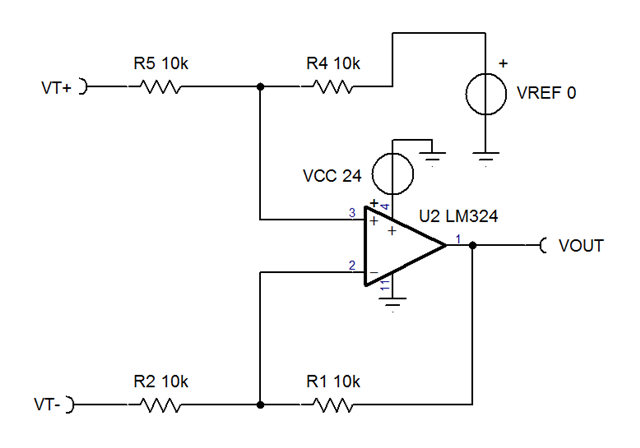
    Use a differential amplifier for each section. An isolated single supply will be fine. The application ground will some connection the the cable ground due to the voltage taps on the cable being an input to the difference amplifiers.

    Here is a gain of 1 diff amp. The supply is 24V to make sure the upper end tap, VT1, is in a valid input common mode range.

    To get lower lower end VT4 being a good input common mode voltage, the application ground needs to connect to VT4 right side.

  • Ron,
    Thank you for the solution! It seems to work in my test circuit for Goal 1. To clarify, when you say 'application ground', are you referring to pin 11? So you are saying VT4_minus needs to be connected to pin 11? Is VREF ground connected to pin 11 as well?

    For Goal 2, subtracting two voltage taps (e.g. VT2-VT3), do I just feed the output of two of these circuits into a third identical circuit?
  • Ben,

    Yes; pin 11 is ground for application. Vref can be also be ground, because  VOUT = (IN+ - IN-) *1 + Vref.

    Note that VOUT may not go lower than 0.7V due to the current demand of the feedback resistors. This would not happen on a different amplifier such as TLV4170

    It is best if VT4- is also same as pin 11 node. In the Ti-Tina file there is a RG resistor at 100 ohms. 0 ohms would be better.

    4 diff amp.TSC