This thread has been locked.

If you have a related question, please click the "Ask a related question" button in the top right corner. The newly created question will be automatically linked to this question.

OPA381: Autozero operation - photoconductive mode TIA - single ended supply

Part Number: OPA381
Other Parts Discussed in Thread: AFE4490, OPA320, OPA376

OPA381 autozero glitch.docx

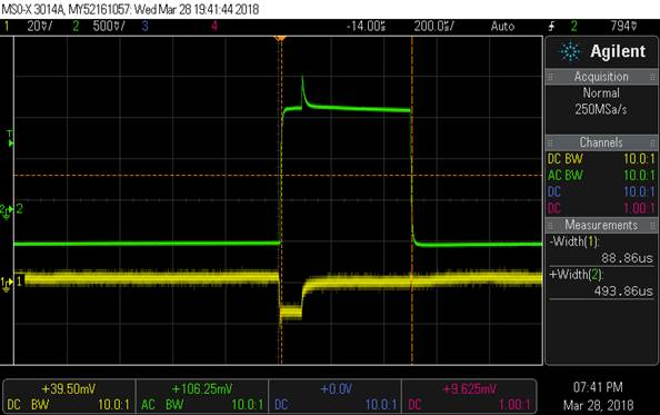
I have run into a difficult to explain situation with the OPA381 in a simple TIA configuration with a photodiode in zero-bias photoconductive mode. The system is using a Thorlabs IS236A integrating sphere with an SM05PD1B photodiode. A 660nm red LED is being pulsed at 500Hz (500usec PW) at the input of the integrating sphere using the TI AFE4490 EVM. When the integrating sphere is completely closed with the LED at one input port and measuring the photodiode output, there are what appear to be ~100usec auto-zero glitches at the TIA input and output. Please see below:


In the following scope shot traces: Yellow = TIA inverting input, Green = TIA output


In this shot, sphere is open to ambient light @ one of the ports while measuring the RED LED – all seems normal . . .


In this shot, all integrating sphere ports are closed while measuring the red LED.  Yellow trace is TIA input and the voltage should always be zero (i.e. zero-bias action of op-amp summing junction).  In this case it looks like an autozero is performed that also glitches the output.  Not much detail on autozero in datasheet other than it is proprietary and takes about 100usec. From what I know about chopper stabilized amplifiers, the glitch at the input appears to be an autozero attempt.


This is very repeatable and seems to be related to the dark condition of a totally enclosed integrating sphere.


My questions are:

  1. Does it seem that this is an artifact of autozero operation?
  2. Am I required to use reverse bias as in figure 4 of the data sheet when operating from a single ended supply? Would this eliminate the glitch I am seeing here?


  • Hi Jim,

    yes, this comes from the autozero operation! The only way to reduce the impact of autozeroing on the output signal is by introducing a sort of low pass filtering.

    I don't think that applying a bias to the + input will eliminate the spikes you observed. Applying a bias is only used to make the photo diode work with a non zero reverse voltage, which decreases the photodiode's junction capacitance and speeds up the photodiode.

    Kai
  • Hi Jim,

    The OPA381 does use autozero technology to attain very low voltage offset levels. In applications where a very high value feedback resistor is employed such as a TIA, the small changes in the input bias current occuring during the autozero switching cycles are converted to voltage changes at the amplifier output. When seen, they usually have a spike-like appearance.

    If the input current from the photodiode sensor is high compared to the input bias current the spikes are tiny and very likley won't be observed. But if the sensor is producing a minimal current such as the dark current, or current levels comparable to the input bias current, the spikes may be observed.

    Kai mentioned filtering and that may be an acceptable option, but plan on adding an additional filter stage. There could be a bandwidth limitation with this approach that would preclude it.

    Another option is to use an op amp that doesn't rely upon autozero techniques to achieve very low voltage offset, but instead employ one that uses electronic offset correction techniques to achieve that goal. Some op amps of this kind that may serve well in your TIA application are OPA376 and OPA320. You can find their datasheets here:

    www.ti.com/.../opa376.pdf

    www.ti.com/.../opa320.pdf

    Note that the OPA376 and OPA320 use the conventional op amp pin layout; the OPA381 pin layout is unique because of it unique functionality. Also, the gain-bandwidth of the OPA376 is about a third of the OPA381 which might be an issue. However, the OPA320 has a 20 MHz gain-bandwidth so that is more in line with the OPA381's 18 MHz.

    Regards, Thomas
    Precision Amplifiers Applicaitons Engineering
  • Thanks Thomas –

    So, what I am hearing is that this has more to do with input signal levels that are less than or close to bias currents and is not due to the fact that I am running a single ended supply . . . Does that sound right?
    I was originally thinking that I might be able to just add some bias as in Figure 4 in the datasheet.   Is the Figure 4 circuit likely to provide enough bias current to prevent the spike I am seeing w/ totally closed integrating sphere?  I was thinking I would bias the non-inv input at about 0.3V to bring the baseline signal off ground while maintaining our original dynamic range.
    Slightly restated, do you think the circuit of Figure 4 in the datasheet might prevent large auto-zero spikes when measuring a pulsed photodiode in an integrating sphere?
    Jim
  • Hi Kai -
    Sorry my browser window cut your response off and I only saw Thomas's reply. I asked him the question you appear to have answered.
  • Hi Thomas -
    Sorry my browser window cut off Kai's response and I see that he answered the question about figure 4. I will look into filtering . . .
  • Hi Jim,

    The very low-level current noise is not associated with using a single supply, but is a characteristic of the OPA381 internal autozero circuit operation.

    The biasing information provided in the text associated with Figure 4 increases the reverse bias voltage across the photodiode reducing its capacitance. That is a useful technique for maximizing bandwidth. It does state that adding the RC at the non-inverting input reduces noise. If it does have any effect on the switching current noise it would only be that associated with the non-inverting input.

    Regards, Thomas
    Precision Amplifiers Applications Engineering
  • Hi Jim,

    We would like to close out this thread. Do you have everything you need?

    Regards, Thomas
    Precision Amplifiers Applications Engineering
  • Thanks Tomas,

    I have a workable solution, but a couple of questions in the attached doc. 

    I may ultimately give the OPA320 a try, but would like to understand the OPA318 autozero a bit better as it is not only the TIA in this test circuit, but also the TIA in our product, 

    Thanks again for your time,

    JimOPA381 autozero glitch-2.docx

  • please note that power level differences in doc on previous post are of no consequence - simply measured at different distances from integrating sphere.
  • Hi Jim,

    hhm, why are the assumed autozero spikes totally synchronous to your 500Hz signal pulses? They should occur at a 10kHz rate. But they are such synchronous to your 500Hz signal pulses, that they seem to be a part of your signal.

    I'm not very familiar with autozeroing. But datasheet says that there's virtually no fundamental noise energy present at the autozeroing frequency (10kHz) due to internal filtering. This makes me think, that the autozeroing is carried out in the servo you can see in the schematic of chip on page 1 of datasheet: The servo compares the inverting input of OPAmp with the ideal GND potential at pin 3 and feeds an integrator with the difference of both potentials. The offset voltage of this servo is made perfect by the autozeroing. And the output of integrator, cleared up from any unwanted offset voltage is finally applied to the non-inverting input of OPamp to correct the input offset voltage of this OPAmp. So, not the OPAamp wired as TIA is autozeroed but the servo, which corrects the offset error of TIA. Very clever! You can run the OPAmp as pure TIA, but have at the same time the ultra low offset of an autozeroed OPAamp.

    Kai

  • Hi Kai,

    Thanks for the autozero explanation - I totally missed the fact that the servo is shown on the pg1 diagram!

    I am not absolutely sure that it is autozero causing this, but there is nothing in the AFE4490 LED driver that would do this as far as I can tell and it goes away with a change in photodiode bias.  The thought is that the sudden change from perfectly dark in the integrating sphere to lots of light is somehow producing this one big shift.  When biased electronically (by intentional offset at non-inv input) or photometrically (by allowing some ambient light into the integrating sphere), the glitch goes away.  The key thing that leads me to believe it is autozero is that the non-inverting input (yellow trace, below) is perturbed for ~100usec, and only at that one point when changing from near zero photodiode current to some higher current.  Since I am running from a single supply, I was thinking that maybe the autozero circuit needed some room below ground to function properly at ground - note that the non-inv input drops below ground, but there is no negative supply! (maybe integrating cap action).  Since I did not have a negative supply available, I decided to bias the diode above ground.  This has cleared up the glitch, but I don't know exactly why - just guessing it has to do with operating near the rail.  I guess I could try adding a negative supply and keep the zero bias to see if autozero is having an issue running at the ground rail . . .  my next experiment when I can get some tech time allotted.

    Any thoughts on whether this is possibly an issue with autozero at the ground rail in a single supply configuration?  It only happens when shifting from true dark current (closed integrating sphere) to some level of light.

  • Hi Jim,

    I have been reviewing your OPA381 autozero glitch-2 document and have noted your questions. Here are my responses to them:

    Not sure I know exactly why, but adding the bias circuit with a simple forward biased Schottky fixed the problem.  It might be that the filtering at the non-inv input prevents the autozero from triggering at transition from dark current segments of the waveform?

    The glitch might actually be related to the output. When you have the input common-mode voltage set to 0 V, the output will be forced to the negative output swing rail. The datasheet Electrical Characteristics table provides some information such as Voltage Output Swing from Negative Rail, RL = 10kΩ, 30 to 50 mV. The output referred voltage offset can add to the issue. Running the output into a rail has recovery implications and the spike might be one of them.

    Moving the common-mode voltage up a few hundred millivolts moves the output off the rail into the linear swing region. No recovery required in that case.

    It seems that the autozero circuit operation is proprietary according to the datasheet – Is it, in fact, running all the time, or only under certain conditions at the input?

    The auto-zeroing process is continuous.

    Are there any app notes that give a little more info on how the autozero works?

    Here are a couple of resources -

    Regards, Thomas

    Precision Amplifiers Applications Engineering

  • Hi Thomas,

    you wrote:

    "The glitch might actually be related to the output. When you have the input common-mode voltage set to 0 V, the output will be forced to the negative output swing rail. The datasheet Electrical Characteristics table provides some information such as Voltage Output Swing from Negative Rail, RL = 10kΩ, 30 to 50 mV. The output referred voltage offset can add to the issue. Running the output into a rail has recovery implications and the spike might be one of them.

    Moving the common-mode voltage up a few hundred millivolts moves the output off the rail into the linear swing region. No recovery required in that case."

    You are briliiant, Thomas! :-)

    Kai
  • Hi Thomas,

    I think your analysis is spot-on and I appreciate the quick and professional response.

    We are OK to close this one out  . . .

    Thanks again,

    Jim

  • And thank you also, Kai . . .

    Jim
  • Hi Jim,

    Glad I could help resolve this OPA381 application. And thanks to Kai for his inputs!

    I'll close this one out.

    Regards, Thomas

    Precision Amplifiers Applications Engineering