This thread has been locked.

If you have a related question, please click the "Ask a related question" button in the top right corner. The newly created question will be automatically linked to this question.

LM7332: Unity gain buffer problem

Part Number: LM7332

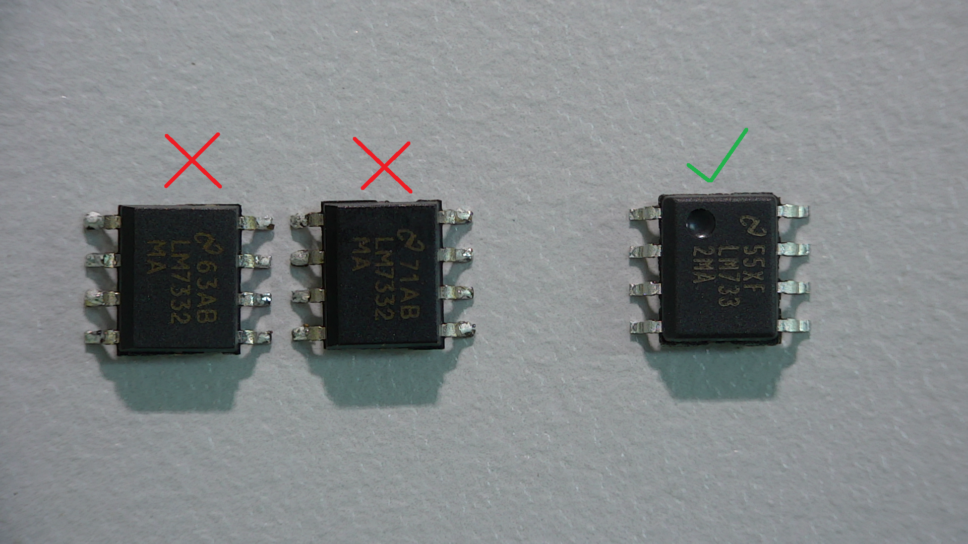
A unity gain buffer using the original packaged format IC (Full dimple on pin 1) has been operational for years in current product. The new batch of ICs with the new (Chamfered) package appear to provide an output 1.5 times the input to the follower (Especially when no input signal is applied), resulting in incorrect performance of the product. This is a certified product for explosive environments and such change is quite alarming.

Could someone please explain the above phenomenon? Has there been a silicon "upgrade"?

Further info: UA is used as the unity gain buffer with pin 1 connected to pin 2. Pin 3 serves as the input and is biased to ground with a 1M resistor and a 100nF Cap. The output of UA drives the input of UB (pin 6) which is configured as a comparator. The IC is powered by a single ended 6V supply.

Many thanks. Any information highly appreciated.

Panos

  • Hello Panos,

    We will check with our quality and manufacturing teams to understand if anything has changed recently with this product.  Would it be possible to share the full part number for the LM7332 you're purchasing along with images of the two different devices showing the top-side markings?

    The LM7332 has a max input bias current of +/-2uA and with a 1MOhm biasing resistor I would expect +/-2V of input bias current related output error which is likely what you're seeing.  The input signal likely has a lower source impedance and when it is connected to the IN+ pin the input bias current flows through it instead of the 1M resistor resulting in a smaller output error.

    Can you replace the 1M resistor with a 1k resistor for testing purposes to see if the output error is reduced?

  • Hi Collin, many thanks for your reply.

    I understand your point about the 1M resistor bias to ground, however this circuit has been working perfectly well up to now. Original package IC measured voltage output (pin 1) is 0.875V; New package IC output (pin 1) is 1.398V.

    All products with the latter package have failed production test. The IC in question is used in two different boards of the instrument, resulting in both boards failing production test.

    Please see below the package that works, and those that do not (Marked X). These are: LM7332MAX.

    Many thanks for your help

    Panos

  • Panos,

    Thank you for the fast images. We should be able to pull the date codes and work with our internal teams to understand if anything has changed.

    Can you confirm if the voltages you've mentioned are measured with the input signal connected, or disconnected? What is the source impedance of the input source? Is it from a high-Z sensor, or is it from a low-Z source like the output of an op amp or lab equipment?
  • Panos,

    We've looked into this inquiry and the beveled edge doesn't match our records for this device. I'm going to send you a "friend request" so we can share private messages off the public forum.

    I'll be asking you also send us images of the bottom of the trouble IC's, an image of the barcode for the reel/tube/ESD bag, and the shipping/purchasing information if you'd like to start getting this information together.
  • Panos,

    In order for TI to begin the verification process all of the following information is required. Please review the attached customer letter and provide the required information to ti-counterfeit@list.ti.com.
    Required information
    1) Completed Counterfeit Request Form.
    2) High quality pictures of the bottom & top of the device(s)
    3) High quality pictures of the 2D bar code labels.
    4) Copies/pictures of shipping documents, i.e. packing slip showing the origin of the devices to TI. (If this information cannot be provided we are unable to provide verification due to uncertainties regarding chain of custody of the products.)
    5) Provide device application.
    Once the required information is provided and submitted, your request will be reviewed for verification.
     Important Note: The attachment size limit for the group address (ti-counterfeit@list.ti.com) is 1MB. Email lisam@ti.com, and j-davenport@ti.com if your attachments are larger than 1MB.

     TI strongly encourages you to purchase all your TI parts either directly from TI or from authorized TI distributors (focus.ti.com/.../distribcountryresults.jhtml) and not from the gray market or brokers.

    Counterfeit Validation Form.pdf

  • Hi Collin. Did you get my private message in response to your bevel enquiry?

    Panos

  • Hi Panos,

    I was out of the office yesterday but received your message.  I'll reply on the private thread to explain what's going on.