This thread has been locked.

If you have a related question, please click the "Ask a related question" button in the top right corner. The newly created question will be automatically linked to this question.

OPA336: Stability Analysis

Part Number: OPA336
Other Parts Discussed in Thread: LMV721, OPA364

Team,

My customer is having the following issue:

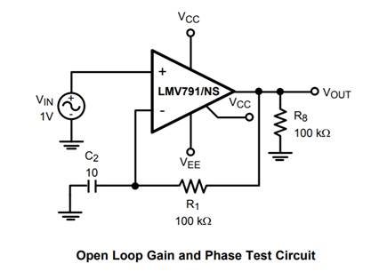
I am trying to run TINA/PSPICE stability analysis on the OPA336 and my plots do not look correct.  I used the circuit below and replaced it with the OPA336 to try and see if my model was the problem and when I plot the response it does not look correct.   Any chance of TI providing the circuit needed to verify the *.lib I am using for simulation?  Feel free to send the TINA circuit if there is one.


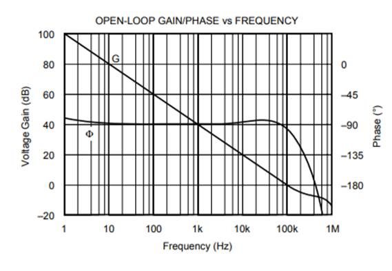
 I was hoping my simulation plot would like this, which is from of the data sheet.  Using PSPICE it is nowhere close so I am not sure this circuit applies for the model I have.

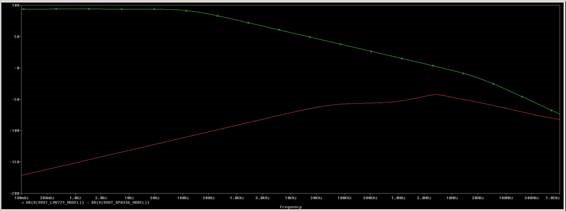
Below is the plot I get using an LMV721(Green) and OPA336(Red) in the test circuit in the original email.  As you can see the OPA336(Red) is nowhere near the LMV721(Green).

I used the circuit in the APPNote below.  Maybe the circuit configuration will not work with the OPA336, which is fine but I just need to know.  I used a different test circuit in PSPICE and got similar results so that is why I was questioning the actual model.  Maybe I cannot do this type of simulation with the current model.


Regards,

Aaron

  • Hi Aaron,

    Can you provide us the actual OPA336 circuit that you attempting to assess in terms of the stability?

    It looks like the OPA336 Pspice model includes the open-loop output impedance (Zo), which is important for an accurate stability analysis.

    Regards, Thomas
    Precision Amplifiers Applications Engineering
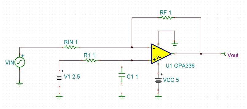
  • Here is the circuit with component values altered so I can send it to you.  The input through RIN comes from the OPA364 on another PBA so they would like the stability analysis run on each circuit.   This is not the circuit used to run the stability analysis, it is the circuit in the design.

  • Hi Aaron,

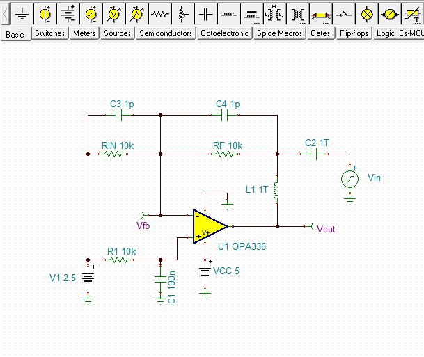
    Okay, the circuit shown is not particularly challenging from a stability standpoint. The OPA336 is unity-gain stable and it isn't driving any kind of capacitive load. Therefore, the circuit should be inherently stable. Nonetheless, I set the TINA circuit up shown below for analysis. The resistors and capacitors in the OPA336 circuit were scaled to practical values. I included some parasitic capacitances across the resistors. The OPA336 model has correct open-loop output impedance (Zo) which is required for an accurate analysis:

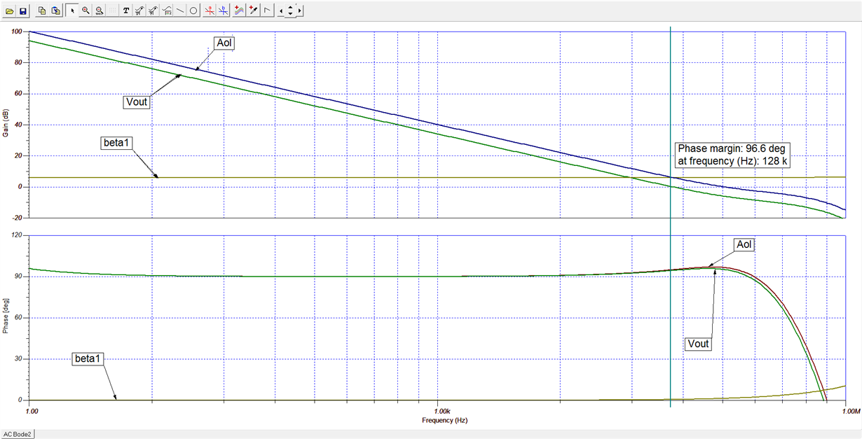
    The gain/phase plots from the analysis are shown here. The phase margin is in excees of 90-degrees indicating that there isn't reason for a stability concern.

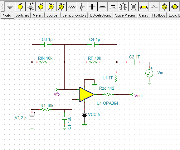
    The OPA364 is also unity-gain stable. It has an older hybrid simulation model and that required a small tweek to get the Zo correct. We have measured Zo data to work from and all I had to do was simply add a 142 Ohm resistor in series with the output to correct the Zo. Here is the TINA circuit that was used to evaluate the OPA364 stability:

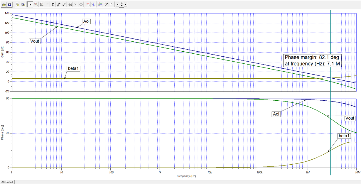
    The results from this stability analysis indicates a phase margin of 82-degrees. Again, there is no concern regarding stability for the OPA364 circuit too.

    Regards, Thomas

    Precision Amplifiers Applications Engineering

  • Mr. Kuehl,

    DId you run the analysis using the full version of TINA? I reviewed the TI webcast that covers the stability analysis and my version(Basic) did not have the AC analysis options that the webcast had. I would like to repeat your plots on our side to verify the model but I am not sure I have the option.

    Thanks for getting back,
    Eric
  • Hello Eric,

    I did use the TINA Industrial version when I performed the original stability analyis. However, I just reran the analysis using the free TINA TI version and obtained the same results. It has all the necessary analysis capabilities to perform this level of analysis.

    The key to obtaining the Bode plots is to access Analysis > AC Analysis > AC Transfer Characteristic... Select Amplitude and Phase, then click on the OK box. The mathematical operations used to create the inverse feedback factor (1/beta) and loop gain curves utilize the Post Processor function on the Bode plot page. The Post Processor icon appears as a "+" sign adjacent to a stack of three cosine waves.

    Regards, Thomas

    Precision Amplifiers Applications Engineering

  • I duplicated the circuit you have in this thread and TINA cannot find the DC operating point.  The previous circuit I used found the DC operating point but the Bode plot looked nothing like the one in the thread. 

    The current circuit(no operating point) is the circuit from the reference design from the OPA336 website.  Not sure why it can find the operating point with my original circuit but not the one where I started from the reference design.  I did run the reference design prior to making the edits and the simulation ran.

    I used the reference design because my current install of TINA does not have the OPA336 in the Spice Macros -> Operational Amplifiers pop-up and I still think there is something going on with my model/setup.

    In the meantime I will check using PSPICE.

    Thanks
    Eric

  • OK I started with the OPA364 circuit and that matched so I swapped out the lib file and renamed it to OPA336 and now I get the same plot. No action needed on your end. Not sure why my original circuit was not working but I think I have it now.

    Thanks
    Eric
  • Hi Eric,

    Great! Thanks for getting back to me and letting me know you made good progress with the OPA364 and OPA336 simulations.

    I'll go ahead and close out this thread providing you are good to go now.

    Regards, Thomas

    Precision Amplifiers Applications Engineering