This thread has been locked.

If you have a related question, please click the "Ask a related question" button in the top right corner. The newly created question will be automatically linked to this question.

CCS/OPA4140: OPA4140 overcurrent

Part Number: OPA4140
Other Parts Discussed in Thread: CC2541, , TPS65133, TINA-TI, OPA137, OPA140

Tool/software: Code Composer Studio

Dear TI officer and members,

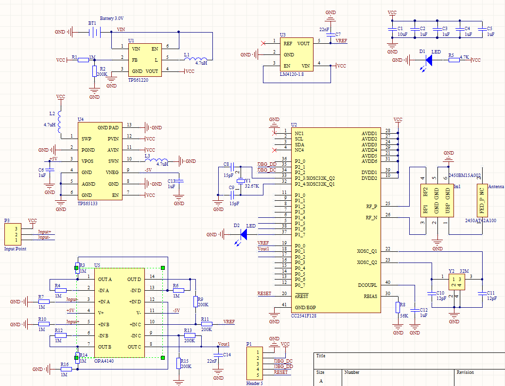
Currently, I am using the CC2541 to collect an analog signal.

The amplifier of OPA4140 was adapted as shown in the listed figure.

Here is the problem that the OPA4140 is every hot (close to 80 C in the ambient environment of 25 C) due to the large input current of 120 mA, which is overcurrent.

This is impossible under the normal condition. I can not find the reason. Please help me.

The positive and negative voltages are provided by TPS65133 dual-output supply.

Best regards,

Derrick

  • Derrick

    When you say input current I assume you mean supply current. The only way you could get that type of current on the opamp inputs is to have an input signal exceed the supply voltage which would forward bias the ESD diodes.

    Your circuit may be oscillating. Look at the outputs of each of the amplifiers with an oscilloscope.

    Regards
    Dennis
  • Your op amps by inspection are not stable. See the following for stability information:
    training.ti.com/ti-precision-labs-op-amps
    10. TI Precision Labs - Op Amps: Stability
    In addition consider downloading the free SPICE simulator from TI, TINA-TI at:
    http://www.ti.com/tool/tina-ti
    By building and simulating your circuit in TINA-TI many problems can be avoided before building it in the real world. If you have problems once the circuit is built in TINA-TI feel free to post the schematic from TINA-TI on the E2E Forum for further assistance.
  • Dear Green,

    Thanks so much for your information. I built the model in TINA-TI. But the ERC always told me the invalid device. Can you help me resolve this problem? thank so much.

    Best regards,

    Derrick

     1881.Noname.TSC

  • Dear Dennis,
    Thansk so much for your reply. Actually, the input signal between pin 3 and pin 5 is NC. hence the input signal is 0 and the supply current is still very large. I can not find the reason. can I change the OPA4140 to another chip to resolve this problem?
  • I changed the OPA140 to OPA137. the circuit works and the output waveforms look good with the 50 Hz sine input. It looks like the op amps are stable.
    But practically the OPA 4140 will be very hot due to the overcurrent. Once I removed the OPA4140 from the PCB board. everything is fine. I checked that the pins connection are good and not shorcircuit.
  • If you study the recommended material you will find the circuits are not stable with OPA140 but will be stable with OPA137. Your resistor values of 1MEG are very high and you will have large noise in your circuit. A capacitor right on the output of the op amp is NEVER a good idea.
    Your design can all be done by simulation to prove correct operation. You can model ADC input and make sure op amp settles at the end of the ADC acquisition time.
    What signal connects to the discrete instrumentation amplifier you built? Sensor? What voltages are you reading differentially into these inputs? What common mode is on these inputs - a bridge sensor?

    Look at the following:
    training.ti.com/ti-precision-labs-op-amps
    10. TI Precision Labs - Op Amps: Stability
    training.ti.com/ti-precision-labs-adcs
  • Dear Green,

    Thanks so much for your help. You are right. The noise is very large due to the MEG resistor. In order to reduce the noise, how many value resistance you recommend?

    This circuit is used to be a sensor for input voltage range from -0.2- +0.2 V.

    Many thanks!