This thread has been locked.

If you have a related question, please click the "Ask a related question" button in the top right corner. The newly created question will be automatically linked to this question.

OPA348: EMI filtering

Part Number: OPA348
Other Parts Discussed in Thread: TLV6001

Hi,

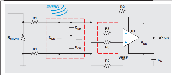
The OPA348 part has internal CM and DM filters builtin , but my deisgn has external CCM ,CDM capacitors with series resistors as shown in the image.

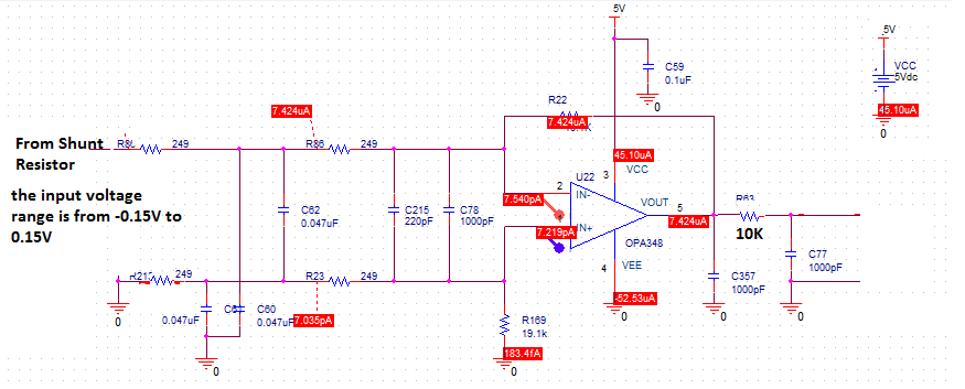
The circuit is built for current measurement across the shunt resistor. I am using the maximum inverting  Input voltage to the circuit is 150mV with the single supply of 5V. the Non inverting input is 0.

Is it really needed to have external EMI filter for the OPA348 part with the above said conditions

Regards

Gayathri

  • Hi Gayathri,

    the OPA348 has internal filters? What do you mean by that?

    Can you show us a full schematic? The Ccm caps could destabilize your OPA348 circuit...

    Kai
  • Hi Gayathri,

    To my knowledge the OPA348 does not have internal EMI filters. If you would like to add external EMI filters I recommend placing them between resistor R3 and the inputs to the op amp to help filter out any high frequency signal before the signals get to the op amp inputs. However, as Kai has mentioned this could degrade the phase margin of the op amp and create stability issues. For more information on op amp stability I recommend watching TI Precision Lab Videos on Stability.

    Another option would be to use the TLV6001 which is a pin to pin, lower offset, and lower noise device than the OPA348 and the TLV6001 has internal EMI filters.

    Thank you,

    Tim Claycomb

  • Hi

    Thanks for your reply. attached is the design circuit.

    can you send me the link of reference document to calculate the phase and gain margain with the filters added.

    Let me know if the circuit attached can cause any stability issues.

    Regards

    gayathri

  • Hi Gayathri,

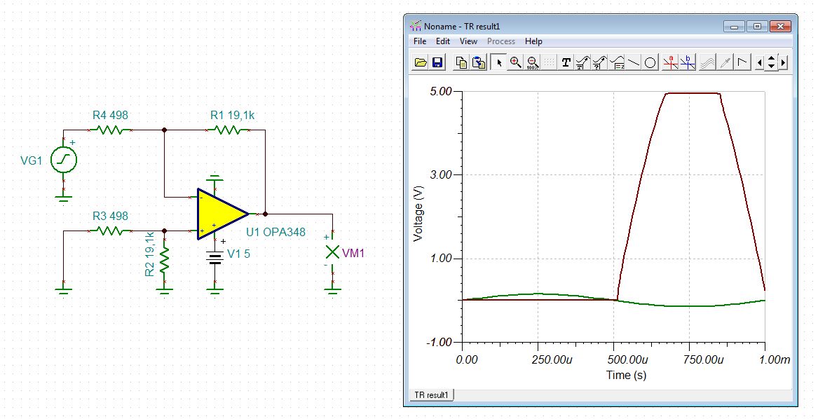
    this circuit cannot handle an input signal of +/-0.15V:

    Kai

  • Hi Gayathri,

    Kai is correct. For the circuit to operate properly with a +/-0.15V input the gain must be reduced and a reference voltage will need to be added.

    I recommend taking a look at our Analog Engineer's Circuit Cookbook for help designing your circuit. The Low-Side, Bidirectional Current Sensing Circuit will likely be the most helpful for you.

    For how to perform a stability analysis I recommend watching our TI Precision Lab videos on op amp Stability.

    Thank you,

    Tim Claycomb