This thread has been locked.

If you have a related question, please click the "Ask a related question" button in the top right corner. The newly created question will be automatically linked to this question.

INA282: Measurement of voltage and current

Part Number: INA282
Other Parts Discussed in Thread: INA190, INA190EVM

Hello, 

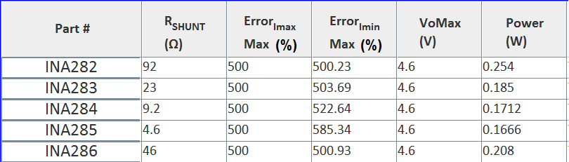
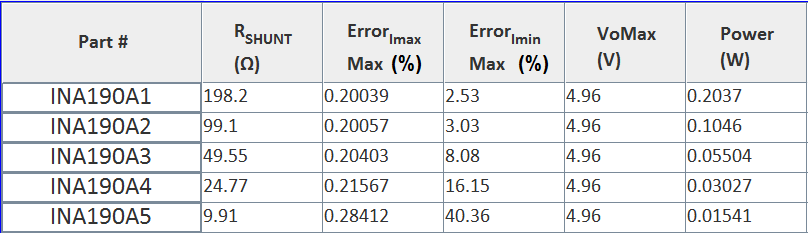
 I just plan to use the  INA282-286EVM kit, what we need to measure is the sleep current the range is around 5uA to 1000uA   The Input voltage is between 12-14 V.

The current is a DC Current. Also , can you suggest a configuration and the INA 28X necessary to use the kit?

Thanks in advance

  • Hello Silvia,

    Thanks for considering to use Texas Instruments in your design.  Those current levels are pretty low.  Below is a table of values I get assuming a supply of 5V for the Errors you will see at both ends of the range.  Typically accuracy improves for larger currents.  Part of the reason you can potentially see such a large error for lower currents is the offset voltage and the input bias current.  The majority of the error in the calculation below can be attributed to input bias current which can be 5x greater than your lowest current (5uA).  If you are trying to measure into the low uA range with precision, I would recommend the INA190 as it has been tailored to have ultra low input bias current and input offset voltage.

  • Thanks Patrick! 

    Thanks for the information. Now I look that you have also a evaluation kit.   the INA190EVM So for the specific test for the current measurement what components should be populate to make the measurement? Beside the R8/Shunt resistor in your feedback?

    Thanks in advance.

    Silvia.

  • Hello Silvia,

    Aside from the shunt resistors, all other components needed for evaluating the board should already be populated. However you can replace some of the 0 ohm resistors and populate the capacitor footprints for input and output filtering. Do not remove the decoupling cap on the supply pin.
  • Thanks a lot of your feedback!