This thread has been locked.

If you have a related question, please click the "Ask a related question" button in the top right corner. The newly created question will be automatically linked to this question.

OP07C: Would you please tell me the reason why 10kohm resisnsatance is necessary between "the Vout " and "- terminal" when op-amp are used for voltage follower ?

Part Number: OP07C
Other Parts Discussed in Thread: OP07D, OP07

Hello

I am electronic engineer using op-amp OP07C

I have some  question abput OP07C

In the  
OP07x Precision Operational Amplifiers datasheet

at page8 

As for the use of voltage follower,

Below figure was drown

Would you please tell me the reason why  10kohm resisnsatance is necessary between "the Vout " and "- terminal" when op-amp are used for voltage follower  ?

I have ever seen "the Vout " and "- terminal" are shorted in many times when op-amp are used for voltage follower.

Will  ""the Vout " and "- terminal" are shorted"" cause some  trouble ?

Would you please explain about diferrence between  "10kohm resistance" and "shorted"

SIncerely yours

  • Hello user5784540,

    It is difficult to know what someone was thinking 35 years ago when the first OP07C datasheet was being developed! I do not find any particular reason why the inclusion of the 10 k feedback resistor in a buffer would be desirable, or necessary. In fact, including the resistor can actually degrade the circuit's phase margin and compromise stability.

    John Caldwell, who used to be one of our Precision Amplifiers Application Engineers before moving to High Speed Amplifiers, penned a useful blog about the buffer feedback resistor subject. He provides a great explanation about the phase margin issue:

    e2e.ti.com/.../resistors-in-the-feedback-of-a-buffer-ask-why

    The bottom line is the resistor isn't needed.

    Regards, Thomas
    Precision Amplifiers Applications Engineering
  • I believe Thomas is correct and would know the TI part better than I but it could be for more than stability (although that is a potential use).  I have seen this done to limit input current due to back-to-back protection diodes on the (+) and (-) inputs.  When there is a possibility of a large and fast change on the (+) input, it takes time for the output to catch up and the maximum differential input voltage spec can be exceeded.  The TI data sheet has a spec of +/- 30V for the absolute maximum input differential so this shouldn't be a problem here. 

    However, I just looked at the OP07D from Analog Devices and the absolute maximum input differential voltage is limited to +/-0.7V.  In this case it is possible that a large fast input signal could cause this specification to be exceeded and cause damage to the part due to the high input current through the protection diode.  Interestingly, I just looked back at the PMI data sheet (8/89) and the spec is also +/- 30V. Something apparently changed when AD bought PMI and this history has probably been lost.  However, this points out the dangers of sourcing "equivalent" parts from various manufacturers.

  • Hi Tim,

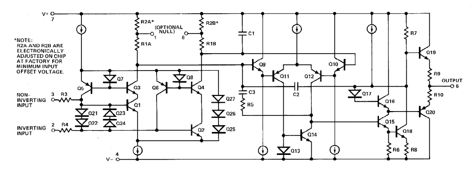
    as far as I know the OP07 contains an input protection circuit like shown here:

    R3 and R4 are arround 500R. This input can withstand high differential input voltages for a brief period, but at the cost of high heat dissipation. So, additionally limiting the input current by the help of a feedback resistance could make sense.

    I also remember that these very low input offset voltage and very low input bias current bipolar OPAmps suffered from ESD. ESD did not necessarily destroy the chip, but the input bias current and input offset voltage could show considerable shifts. One "cure" of that time was to use current limiting resistors in series to the input terminals.

    The OP07 is very slow (bandwidth = 600kHz), so the eroding of phase margin of OP07 due to this 10k feedback resistance might not be too critical. But with faster OPAmps such a 10k feedback can end in a desaster. Because of that it can often be seen, that some capacitance is recommended in parallel to this feedback resistance.

    Kai

  • Looks like the same schematic in the old PMI data book and I agree R3 and R4 are likely for current limiting.  I'm not sure why the current AD part has a +/- 0.7V differential limit.

    For the phase margin issue, if I have the board space I try to include room for the FB resistor and for a series RC network (lead compensation) between the inputs.  That way I can use an uncompensated amplifier if desired.  And as Bob Pease said...always use a small feedback capacitor unless you can prove you don't need it.

    Tim

  • Hi Tim,

    We have had internal discussions about the purpose behind the inclusion of the 10 k resistor in the feedback loop. It has focused on the likelihood of it being included for protection purposes, as has discussed on the E2E. Paul Grohe, of TI's Low Power Amplifiers and Comparators group suggested, "The buffer feedback resistor is normally added for limiting the current into the input stage during full-slew events with a low impedance source… Also helps limit current should the output get shorted or “stuck” with a low impedance source." This was meant as a general comment about some op amps and not necessarily the OP07C. It does appear that the OP07C design with its input clamps and series input resistors should be reasonably sturdy and not needing an external input current limiting resistor.

    I think your idea of including a provision for the feedback resistor and capacitor on the PC board is a good one. I suspect if you use a zero-ohm jumper in the resistor space your probably won't incur failures. However, should the unexpected occur you have it covered. If failures do occur with the zero-ohm jumper in place, then that is something we would really like to hear about here at TI.

    Regards, Thomas
    Precision Amplifiers Applications Engineering
  • Thomas...I appreciate the thorough response. I have used the zero ohm solution for many years and never experienced a problem unless I forget to tell my tech to populate them before testing :)

    Thanks for the discussion,

    Tim
  • Hi Tim,

    Has this OP07C inquiry been satisfactorily addressed? If so, please go ahead and close this E2E thread?

    Thanks, Thomas
    Precision Amplifiers Applications Engineering
  • My apologies Thomas...how do I do that? I'm not seeing anything on this page to close the thread. Perhaps it is because I didn't start the thread?

    Tim
  • Hi Tim,

    Yes, I suspect you are correct; the originator will have to close the inquiry. Sorry about that.

    Thanks for your inputs, they have been helpful!

    Regards, Thomas

    Precision Amplifiers Applications Engineering