This thread has been locked.

If you have a related question, please click the "Ask a related question" button in the top right corner. The newly created question will be automatically linked to this question.

LM224A: LM224AD date codes

Part Number: LM224A

I have parts marked LM224AD that have the same date code but different bottom mold marks.

date code: 

82D1TPK    G4  with bottom embossed mark 03C13

also

82D1TPK    G4  with bottom mark in small molded box 07K02 and several others in similar format

Are both valid for the same lot code?

Also have one of Philippines origin with date code:

83ZDV44   G3   with circular bottom mold mark "PHILIPPINES 248"

are all of these legitimate date codes and marking styles?

i have a design where all the above do not work properly. One other date code seems to function as expected:

86A6P3M  G4  with bottom embossed mark of 2B046


  • John,

    What is the full part number you ordered? I need that to check the all the top symbols for that orderable. At first glance the top symbolization looks correct. Anything on the bottom of the die is not the date code but hard coded on the bottom of the encapsulation tray. In other words it has no useful meaning.

    What are the symptoms of the issue you're encountering?
  • Hi Ron,

    The full part number is LM224ADR. These parts have been ordered in several batches so the inventory information for parts that have already been placed on boards is not available. We are a contract manufacturers and this is a product for one of our customers. This product has been running orders in the 10K to 12K units per year for several years. We had a recent batch of product that had a 10% failure rate on a batch of 1000 units which threw several quality flags. Having tracked down the non-conformity to the parts with the questionable date codes I was trying to determine if these were actually TI parts – since when I replaced them with new parts 10 out of 10 worked as expected. I can’t exactly determine the exact problem due to the nature of the assembly, but the problems could be offset voltage, or common mode noise. One of the stages is a simple buffer with a 5V input from a reference but the output shows what appears to be power supply / cross-over noise from another amp in the package. I know the parts are op amps, but they don’t seem to be good op amps – at least as used in this circuit as compared to our historical experience with these parts. I am building a test circuit to compare operation of the parts.

    I can send you some parts. I have x-rayed them and find that the current working part has a smaller die and lead frame than the non-working parts, although they may just be older revisions.

    Any ideas?

    Thanks,

    John J. Knittle
    <TI removed personal info>

  • John,

    '83ZDV44 G3' text is correct format for the top line
    For '82D1TPK G4' & '86A6P3M G4', did one have G4 on the top line and the other have G4 on the second line?
    The second line for all should be LM224A (and optional G4)
    The die size for all LM224A should be the same if the device has the "A".
  • John,

    The X-ray and package pictures all look good. The die is same same in all X-ray images. The different lead frames used are qualified at the assembly sites that built them.
  • Thanks, Ron!

    Still, I find that the parts with the 82D1TPK date codes are not working as well as the 86A6P3M marked parts. I have a batch of units, now totaling about 300 with the same issue. So far, I've changed ONLY the op amps, and fixed 30 out of 30. I've tried swapping "bad" for "bad" and "bad" for "good" with the problem following the date code.

    The part of the circuit that is the focus of the problem is an Inverting amp with a gain of -1.49 (-69.8K/47K). The non-inverting terminal has a 10KΩ to ground. The input comes from the output winding of an AC current transformer with a 100Ω load resistor - it runs between .85V and 1.95V peak to peak at 60Hz.The op amp output becomes inverted and half-wave rectified due to the ground reference. I built a set of buffer amps using all of the different date coded parts and applied the same function generator signal to all amplifiers - each with its own 1KΩ input resistor. Using a sawtooth input, i was able to discern that the 82D1TPK parts are slight more susceptible (than the 86A6P3M parts) to output inversion when the input goes below ground - but that is the only difference I can find.

    The LMx24 spec shows and absolute max of -0.3V on any input so it looks like the design is slightly out of spec. I'll work with the client to see if we can change either the part or the circuit.

    I appreciate your effort to help me resolve this.

    Thanks,

    John

  • John,

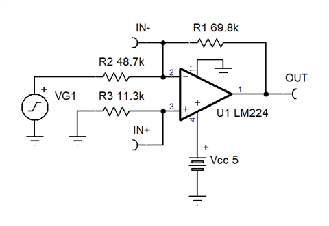
    I tested the circuit you described and chose 5V for the power source. I also had to tweak the values to match my parts on hand.

    Here is my test schematic.


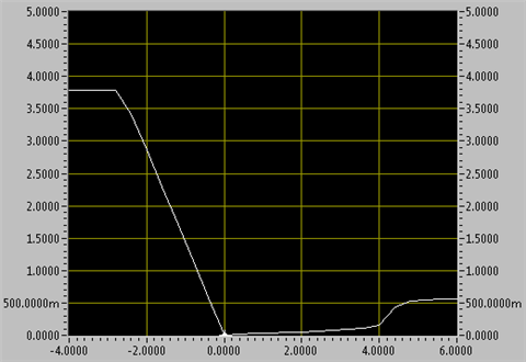
    Here is the DC transfer function VOUT vs. VIN of my setup. (bench data)

    Note that negative voltage gets the correct negative gain until output hits VOH level.

    For positive input voltage, the gain is small and positive based on VOL resistance.

    Eventually the sink driver can’t support the output current (from feedback) and the other LM244A sink driver takes over but it has a larger VOL headroom requirement.

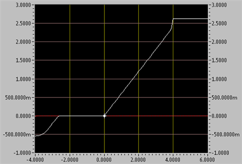
    Here is IN+ (red) and IN- (white) voltage for the same VIN range. (bench data)

    IN- does violate input range, but only for voltage close to -3V or more negative.

    I tried input as large as -40V and output did not invert (on my sample). 

  • Hi Ron,

    Yes, the inverting circuit you tested  is practically immune to inversion; I only found the inversion in my simple buffer test circuit. What I did notice on the inverting circuit, however, was that the current transformer's 2Vp-p signal's positive half-cycle created a hump in the output waveform that the designers most likely intended would be flat (possibly expecting rectification and clamping at 0V for positive signals. Since it is not a flat response, the RMS value of the result is slightly off - my guess is that the different manufacturing dates have slightly different "distortions" in this area. That seems to be the only explanation that I can muster because all of the parts seem to behave as expected when the inputs are within normal ranges.