This thread has been locked.

If you have a related question, please click the "Ask a related question" button in the top right corner. The newly created question will be automatically linked to this question.

OPA4374: Sensor output signal conditioning

Part Number: OPA4374
Other Parts Discussed in Thread: TEST2, TINA-TI

Hi team,

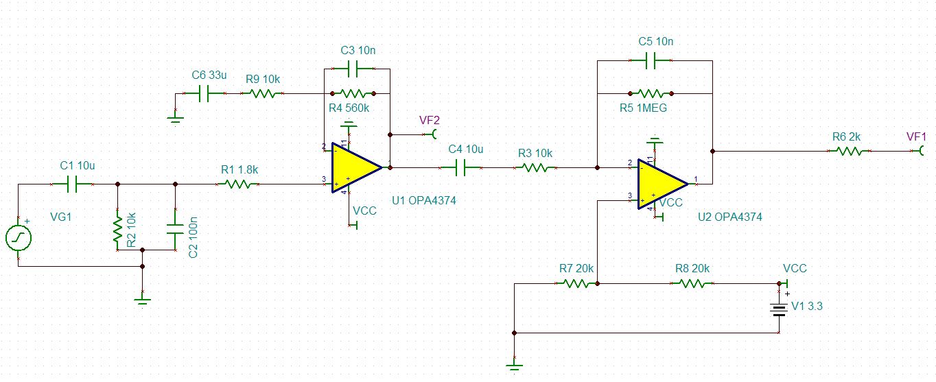
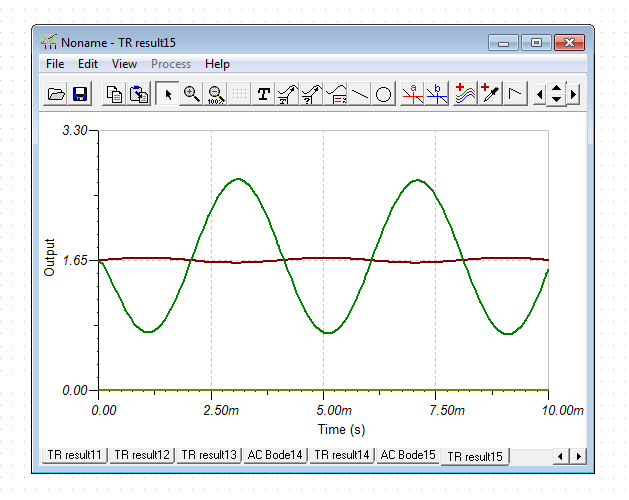
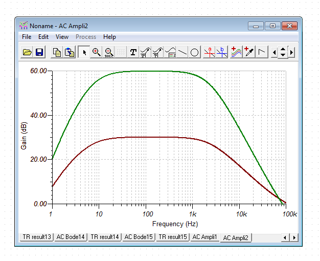
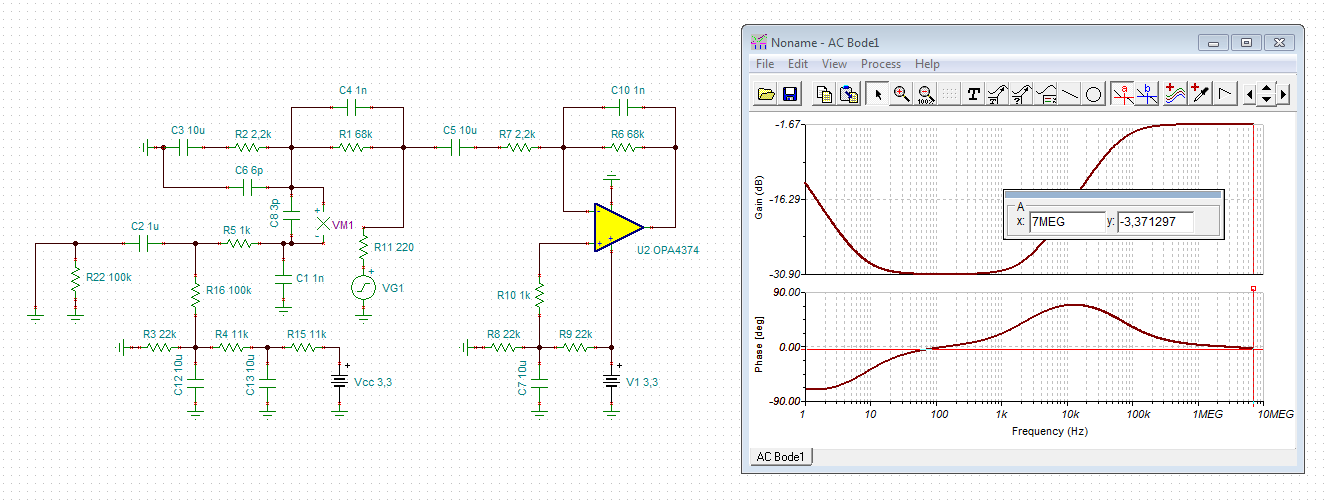
My customer is designing a signal conditioning circuit for sensor signal. They want to use OPA4374 to amplify the input signal, and have this two schematic.

Could you please help to check if these two circuit work? Or do you have a better solution for this application?

Sensor's output: 100-250Hz, 5mV(sine wave); AD range 0-3.3V, 12bit, 250kSPS.

By the way, the sensor is single power supply, so the output should only have the positive voltage.

Thanks!

James

test1.TSC

test2.TSC

  • Hi James,

    your second circuit is working, but your first circuit is not working.

    The sensor signal, does it produce a DC output voltage as shown in your first simulation? Or is it AC only?

    Kai

  • Hi James,

    Welcome back!

    Though your second circuit is working, there is really no use for R3. You may consider removing it unless you plan using a capacitive load.

    While I am working on checking your first circuit, consider dividing and conquering it. Looking at the first stage by itself making sure stability, BW, i/o ranges before adding the next stage.

    I am applying the same rule and will get back to you asap.

    Thanks.

    Regards,

    -Mamadou
  • Hi Kai,

    The sensor output only have AC voltage.

  • Hi Mamadou,

    Thanks for you attention.

    Could you please help to check the first circuit? If they want to use the first circuit, what changes need to be done?
    Or do you have other solution for this sensor output detection?

    Thanks.
  • Hi James,

    your second circuit exactly contains the changes which have to be made to make the first circuit work properly. :-)

    Kai

  • Hi Kai,

    Actually, they need two stage to amplify the input signal. And the input only have the positive voltage.
    And the Sensor output normally is around 1mV, and 5mV is peak voltage. So they want to amplify this 1mV sensor signal.
    Could you please help to recommend a circuit with two stage amplifier with gain of 1000?
    By the way, I don't know if we could not use the band-pass circuit on input stage, in stead of a low-pass circuit?

    Thanks.
  • Hi James,

    what frequency response shall the circuit have? Linear between 100...250Hz and -3dB at 100Hz and -3dB 250Hz?

    Kai
  • Hi Kai,

    Their signal is usually less than 250Hz, and no need to be -3dB at 100Hz and 250Hz.
  • Hi James,

    well, since the amplifier is AC-coupled I need to know a corner frequency of the unavoidable high pass. :-)

    Kai
  • Hi Kai,

    What do you mean by corner frequency unavoidable high pass?
  • Hi James,

    I need to lift up the input voltage (VF2 of second circuit) to VCC/2 by the help of R7 and R8. The -input of OPAmp mirrors this DC voltage due to the feedback provided by R4, R9 and C6. C6 makes that only the AC components of input signal are amplified by the gain set by R4 and R9. The DC part isn't amplified because C6 presents a infinite impedance at DC. So, the gain factor for DC is only 1, while the AC components see a gain set by R4 and R9.

    Now there's a corner frequency, at which the AC gain drops to -3dB. This corner frequency is set by the time constant R9 x C6. Above this corner frequency the AC gain is nearly constant and below this corner frequency the AC gain drops by a slope of 20dB per decade.

    Kai
  • Hi Kai,

    Thanks for the detailed explanation. I didn't get the exact corner frequency from customer, but the useful signal is 100-250Hz. So I suppose we could just keep our corner frequency around 500Hz or 1kHz, and not attenuating the useful frequency signal.

    By the way, they want to design as a two stage amplifying circuit with total gain about 1000, beacuse normally the useful signal is around 1mV. In order to make it easier for ADC to do the sample, it would be better the conditioned signal is a volt magnitude. 

    Thanks.

  • Hi Kai,

    Any feedbacks?

    Thanks.

  • Hi James,

    not knowing your sensor, this circuit could be a good starting point:

    james2.TSC

    Kai

  • Hi Kai,

    Thanks for you detailed schematic.

    I still have a question: durign f=134Hz, Phase=-180, will this cause stability problem?

    NOTE:the useful input signal is 100-250Hz

  • Hi James,

    your plot is showing the phase response of the whole circuit. And because of the use of the inverting amplifier U2 there is a phase shift of 180° between input signal and output signal in the signal frequency range of 100...250Hz. This is absolutely normal.

    The follwing pictures show the result of simplified phase analysis to investigate the phase margin of each OPAmp:

    You can see that the phase margins are ok. But keep in mind that a capacitive load at the output of U2 can change the situation. So, you should repeat the phase analysis when knowing the actual load.

    Kai

  • Hi Kai,

    Do you have a stability analysis for the whole circuit? I know how to set a break point for each amp, but not familiar with two stage amplifiers.

    Thanks.
  • Hi James,

    the above is already a (simplified) stability analysis of the whole circuit, because all of the circuit is involved in the simulation. So far, the circuit should be very stable. But again, for the stability it's of crucial importance what you connect to the output of U2!!!

    Kai

  • Hi James,

    When analysizing a two stage amplifier design for stability you analyze each amplifier seperately as Kai has mentioned. However, I do not recommend using the method Kai has shown because Aol and Zo of the amplifier (both of which are required to simulate stability) is not included in Kai's method.

    I recommend watching our TI Precision Lab videos on stability which explains how to simulate the phase margin of an amplifier in TINA-TI.

    Thank you,

    Tim Claycomb

  • Hi Tim,

    as I said, this is a simplified phase stability analysis. But the open loop output impedance IS included:

    Kai

  • Hi Kai,

    I apologize, I did not notice that was include. However, I still recommend using the method provided in TI Precision Labs. It only requires adding an inductor and cap to the schematic and can provide a much more accurate simulation (assuming the model is correct!).

    Thank you,

    Tim Claycomb

  • Hi Tim,

    Thanks for your recommended method for the simulation.
    question:
    1. If I want to estimate the stability of two-stage amplifier circuit, do I just need to make sure each stage is stable?
    2. If I let the output always be the VCC for the rail-to-rail amplifer, do I need to concern about the Iq or temperature or something?

    Thanks.
  • Hi James,

    1. Yes, for a two stage amplifier design you must make sure each gain stage is stable.

    2. Why would you want the output to always be to Vcc?

    The Iq shouldn't increase with an increase in output voltage but you will have an increase in current consumption if there is a load on the output.

    The temperature of the device will depend on output voltage, ambient temperature, Iq of the device, and the output current during operation. I recommend watching out TI Precision Lab videos on Power and Temperature for more information.

    But again, why would you always keep the output at Vcc?

    Thank you,

    Tim Claycomb

  • Hi Tim,

    Thanks for you information.

    "why would you always keep the output at Vcc?", because they may use a high gain for this circuit, which may lead to the output have the Vcc voltage. And they just need to know when the signal across a certain value, kind of like a comparator.

    Thanks.

  • Hi James,

    I understand now, thank you for the clarification.

    In that case, what I said in my previous response still applies. The Iq shouldn't increase with an increase in output voltage but you will have an increase in current consumption if there is a load on the output.

    The temperature of the device will depend on output voltage, ambient temperature, Iq of the device, and the output current during operation. I recommend watching out TI Precision Lab videos on Power and Temperature for more information.

    Thank you,

    Tim Claycomb

  • Hi James,

    what is the exact load U2 has to drive? You told us that an ADC shall be connected? Can you show us a schematic of the interface circuitry of this ADC?

    Kai