This thread has been locked.

If you have a related question, please click the "Ask a related question" button in the top right corner. The newly created question will be automatically linked to this question.

INA180-181EVM: INA180-181EVM

Part Number: INA180-181EVM
Other Parts Discussed in Thread: INA181, INA180, TINA-TI

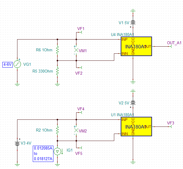
I am using INA181 current sensor. I am facing the problem that it is not giving the desired output. On varing the Input Supply the output is not changing. On giving a few mA current, the output gets saturated to a value. I don't if my circuit connections are wrong or what's the problem. Someone please resolve my issue.

  • Hi Sushant,

    you have drawn a chip with 5 pins. That's not the INA181. Do you mean the INA180?

    Also, you don't have connected a Rsense across the inputs. And where is the lower end of 330R resistor connected to?

    Please have a look into the datasheet to see how the chip has to be wired.

    Kai

  • I had made a circuit which has a power supply and a 330ohm resistance as load. In this circuit, I have connected the current sensor INA180 and for INA181 the 6th pin which is reference pin is connected to common ground.
    I don't know how to connect this Rsense across input and of what rating it should be.
    The lower terminal of 330 ohm resister is connected to negative terminal of supply.

    My aim in this circuit is to give varing current input to the current sensor and observe the respective behavior of its voltage output.
  • Hi Sushant,

    take care, the INA180/181 only withstands an input voltage of 26V. So, a 30V supply as shown in your schematic will be too much.

    The following simulation shows what happens when you connect a Rsense of 1R between the input terminals:

    Whether a Rsense of 1R is a proper value depends on your application and whether the voltage drop across Rsense is tolerable. You can decrease the voltage drop by decreasing Rsense. But then your output voltage also decreases. Also, when decreasing the voltage drop across Rsense the input offset voltage becomes more and more dominant. The input offset voltage of INA180/181 is 500µV maximum and creates an error of up to 1% if the voltage drop across Rsense is 50mV.

    Here's the TINA-TI file:

    sushant.TSC

    Kai

  • Please tell me that how can I vary the Input current in the above circuit. And which of the R5 and R6, is the Rsense?
  • Hi Sushant,

    you told that you want to use a 330R resistor to make a current flow. R5 is this 330R resistor. R6=1R is Rsense.

    Kai
  • Hello Mr. Kai,

    I have done everything exactly as per your instructions. Now the problem is on varing this R5 resistor which is acting as load, the input current is varing but the output volatge remains constant. I have made only one change in the circuit that the V2 is 4V in my circuit.
  • Hello Sushant,

    Thanks for considering to use Texas Instruments. How is your input current varying?  The above diagram corresponds to a single operating condition.   If V2 varied from 4V to 6V or something else, I would expect that you would see the output change.   How I see it there are two ways to observe the device operation.  One is to vary V2, the other is to replace the 330 ohm with an electronic load or potentiometer.  Both of these are illustrated below.

  • Hello Sushant,

    We have not heard from you in a while. If you need further help, please respond below. Otherwise for now, we presume your issue has been resolved.