This thread has been locked.

If you have a related question, please click the "Ask a related question" button in the top right corner. The newly created question will be automatically linked to this question.

TINA/Spice/INA133: Tips to carry out stability analysis for improved howland current source

Other Parts Discussed in Thread: INA133, OPA192, TINA-TI, OPA548

I need to construct a V -> I conversion circuit with a gain of 100mA/V and +-200mA drive capability. The frequency requirements are not high, and bandwidth of 2kHz would more than suffice. However the circuit needs to operate with a wide range of resistive & inductive loads. With an inductance range of 0 to 100mH and resistance of 0.1R to 500R (Understanding that the current will be limited at higher resistances by the +-15V supply rails)

My AC analysis is a bit rusty and I have been trying to work through the guides found here https://training.ti.com/ti-precision-labs-op-amps-stability-3 to calculate the phase margin.

However I am not quite sure the correct location to break the feedback loop at, in particular since the Howland current source also has positive feedback.

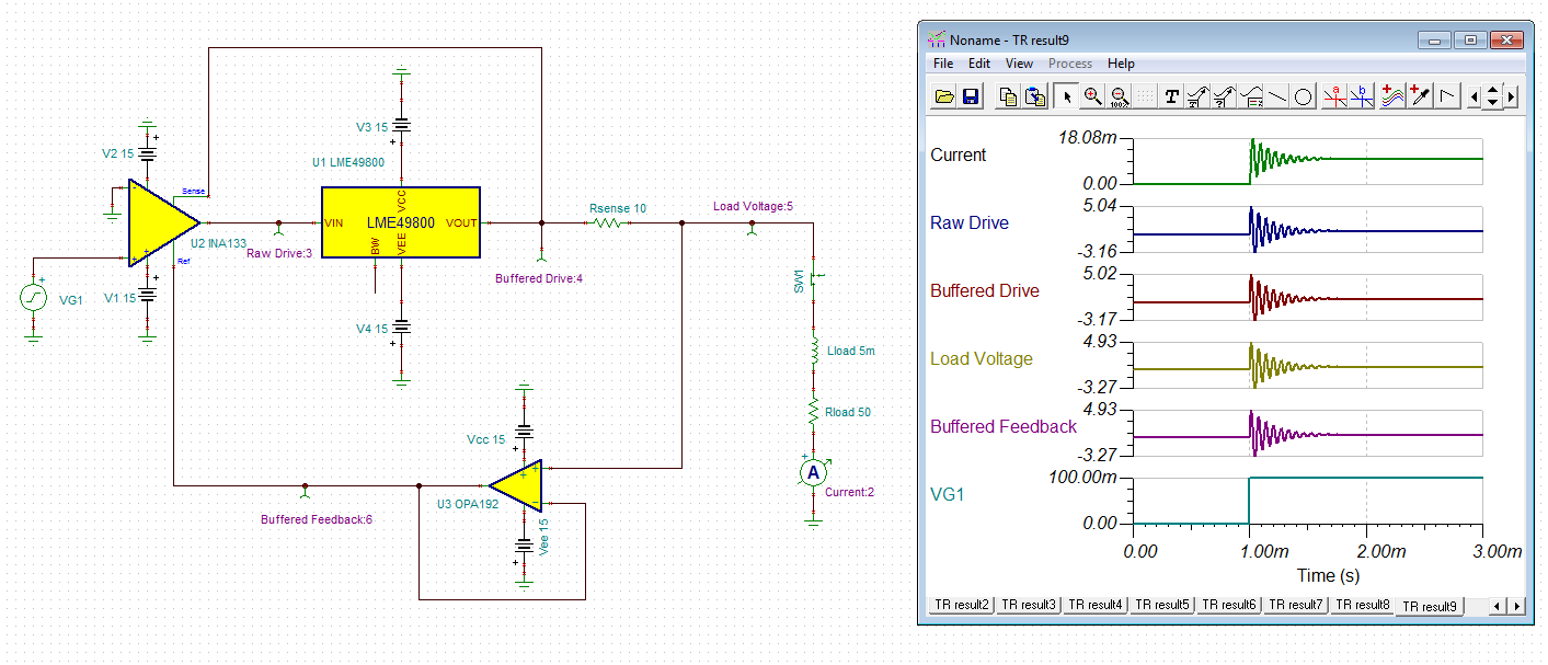
I have attached my TINA simulation.

current driver circuit.TSC

  • Hugh,

    Since your question focuses on the design of the circuit, I will move your inquiry to the Precision forum,
    That forum is monitored by the product experts, who will be better able to help.

    Regards,
    John

  • Hi Hugh,

    the transient analysis shows the following result:

    Hhm, this does not look very stable...

    hugh.TSC

    Kai

  • There are two key presentation I attach for you to study.  The "Design and Apps Current Sources" contains an important section on the Improved Howland Current pump, especially on driving inductive loads. The "Dual FB Beta_plus and Beta_minus" gives an alternate approach to analyzing loop stability for the Howland.  The INA133 the way you are trying to use it is not a good idea. Replace it with an op amp because we will need to be able to use compensation around the op amp . Read through attached and rebuild your concept circuit and re-post and I will help you with the stability.

    8231.Design and Apps Current Sources.ppt

    4048.Dual FB Beta_plus and Beta_minus RevD.pptx

  • Kai, I know its not very stable, and had looked at the transient response, but I didn't know how to go about fixing it.

    Thanks very much tim, I think that info was very useful.

    I have switched over to using another OPA192 to close the loop instead of the INA133.

    I have then run through the referenced material and I would just like to confirm I am understanding the compensation correctly.

    The inductive load is effectively adding a pole to the loop gain plot, causing the phase margin to drop below 45, causing overshoot and/or instability. By adding the RC network to the op-amp + terminal we are adding an additional zero to cancel out the phase shift of the pole from the inductive load. Therefore to ensure stability I need to insert the zero at around the frequency of our coil with the lowest resonant frequency.

    The Ro value is in place because voltage source we are using to split things is ideal, and Ro is just being used to emulate losses in the output stage of the op-amp.

    Does this all sound about right?

    With the compensation added I can get the following open loop response plots.

    Assuming I have simulated this correctly now only the purely restive case is on the edge of acceptable.

    Transient response also looks better, it looks like there are some effects going on with recovery times when the driver stage is saturating but I suspect I can clean that up with a resistor and some zenners between stages.

    As a side issue is there any way to get the post processing curves to work with stepped parameters instead of having to do a bunch of manual cleanup on each plot.

  • Hi Hugh,

    when you have opened TINA-TI click onto the tab "Analysis". Then click onto "Select Control Object". Click with the left mouse key onto the component you want to be stepped. A window will open. Finally click on the button "Select..." and enter the desired parameter settings.

    Kai
  • Hi Hugh again,

    by the way, what speaks against the use of OPA548 in your Howland Current Source?

    e2e.ti.com/.../673984

    Kai
  • Hi Kia

    I have used the parameter stepping before I was just asking after a way to have it so if I define a curve is post processing i.e. if I define Aol = VO(s)/Vbeta(s) and simulate a single step, if I then enable parameter stepping my VO(s) turns into VO[1](s), VO[2](s) etc and the extra curves error out. I was after a smart way to have it create the Aol, and 1/B curves for each of my parameter steps.

    I didn't select the OPA548 due to its large offset voltage (would cause up to 0.2mA offset in our use case). I also didn't want to use it as a buffer as I wanted to avoid having to deal with the extra phase shift. It is also much pricier than the buffer I used in my circuit.

  • Hugh

    We haven't heard back from you so we assume you were able to resolve your issue. If not, just post another reply below.

    Thanks
    Dennis