This thread has been locked.

If you have a related question, please click the "Ask a related question" button in the top right corner. The newly created question will be automatically linked to this question.

OPA838: Is this the appropriate part for this application

Part Number: OPA838
Other Parts Discussed in Thread: OPA615, TINA-TI

Hi - I have a signal that varies between 2MHz and 30MHz and can also vary in amplitude between 100mV peak to peak and 1000mV peak to peak.  I'm attempting to count pulses using a counter IC which requires input levels of 1.5V (maximum low level) to 3.5V (minimum high level).  I was looking at the OPA838 as a possible mechanism to accomplish amplifying the signal.  For example using a single supply of 5V, setting AREF to 2.5V and a gain of 5 - this would work for the whole frequency range but only for higher amplitude signals (i.e. it won't work below 400mV p-p).  Is there a way to use the OPA838 and have variable gain?  Is there some other IC that is a better choice?  Any help would be appreciated - thanks.

  • Hi David,

    You can use a sample and hold capable device such as the OPA615 for peak detection, but if the pulses are frequent, and your IC input is digital, you may want to use a high speed comparator like TL14C instead. Op Amps are for for analog to digital converters.

    Best regards,

    Sean
  • Hi David,

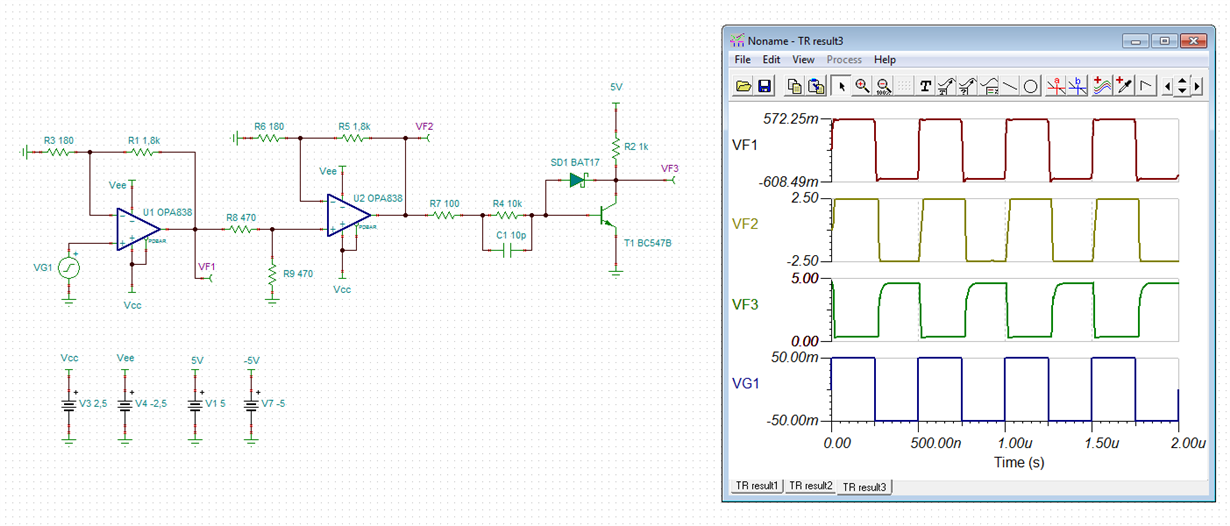
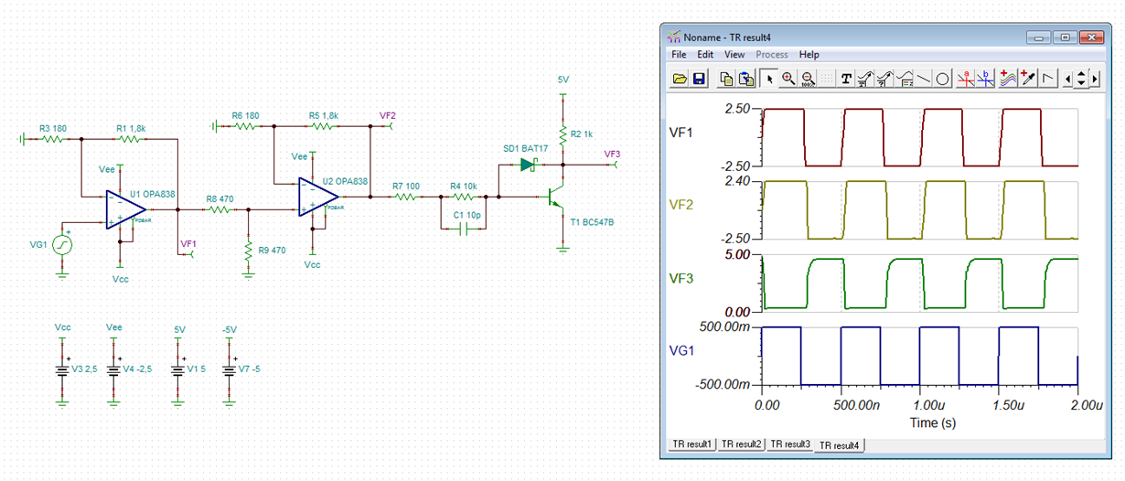
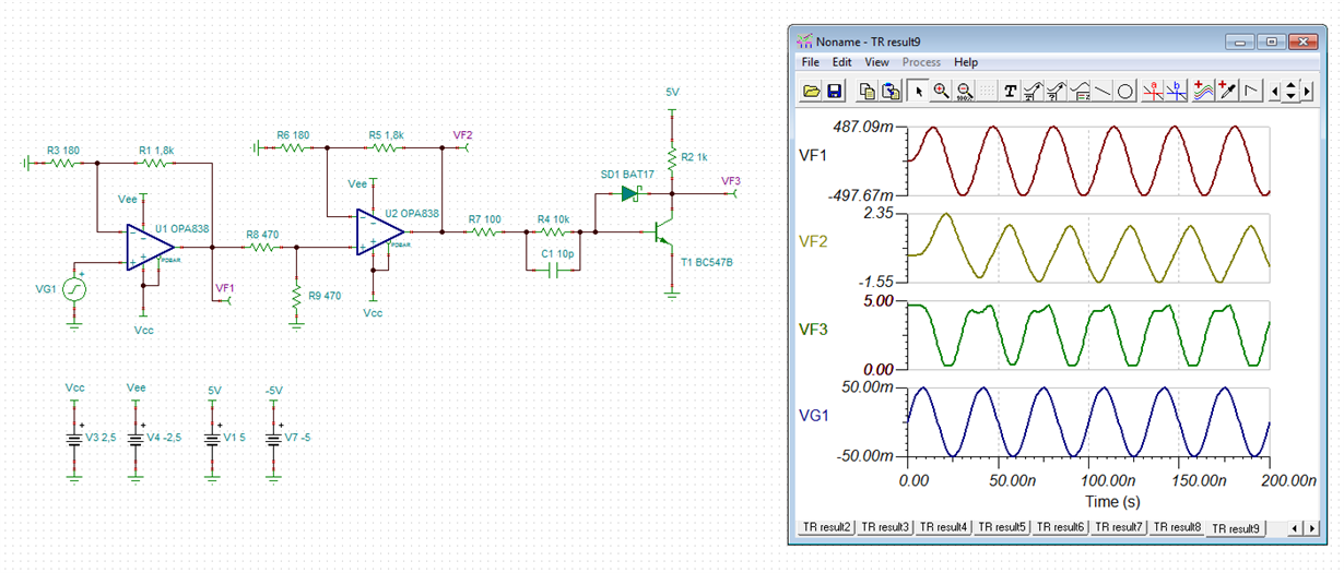
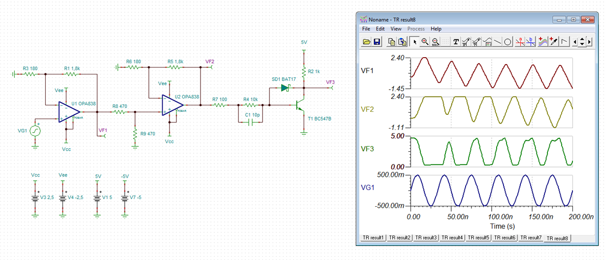
    I have made a few simulations. The following scheme could work. First some 2MHz and 30MHz square waves:

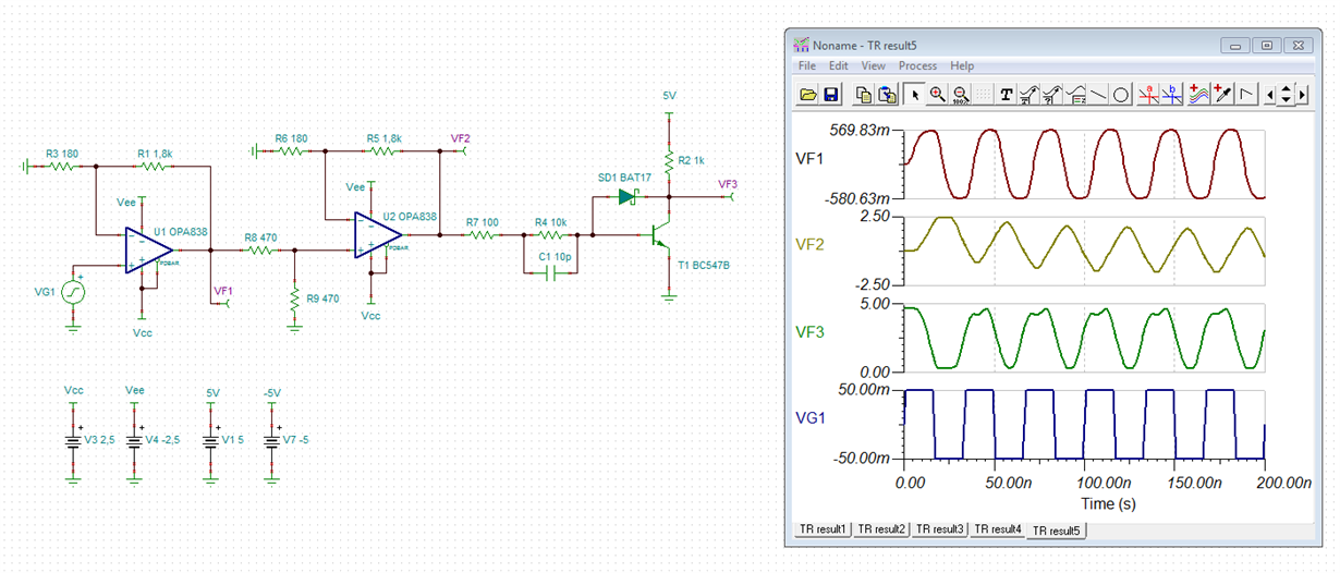
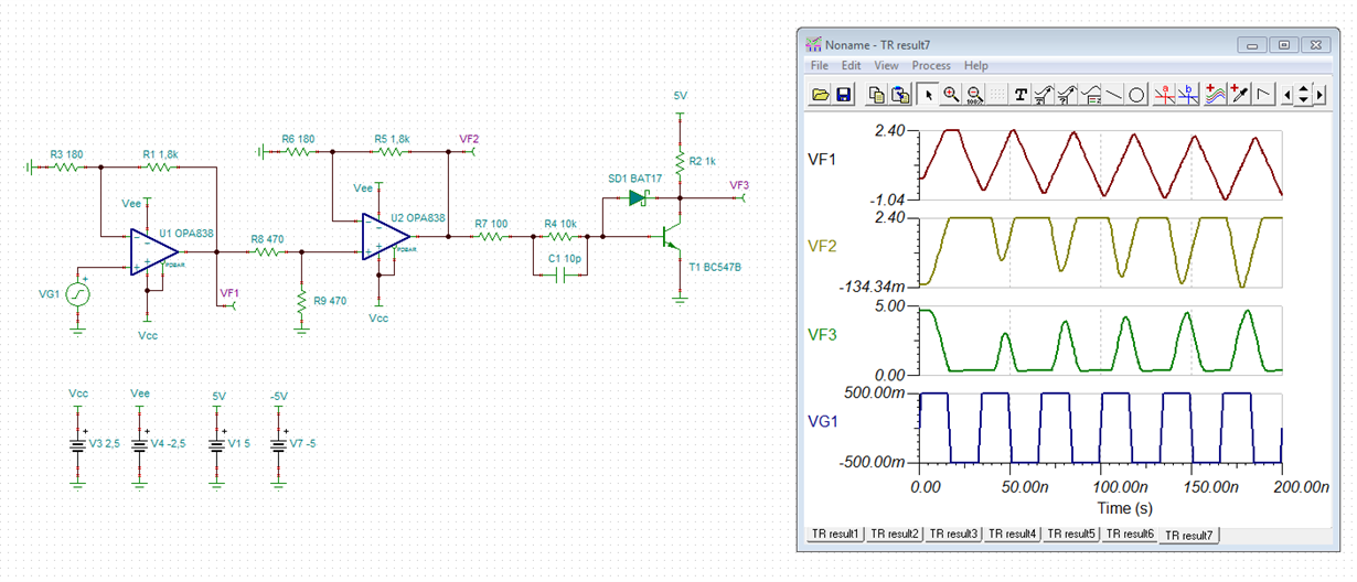
    And finally a 2MHz and 30MHz sine wave:

    hrivnak.TSC

    Kai

  • Hi David,

    some words about the circuit:

    The circuit is DC coupled. Two OPA838 are cascaded to get the necessary gain to be able to fully turn-on T1. R8 and R9 decrease the output signal of U1 to prevent the input signal of U2 from exceeding the common mode input voltage range of OPA838. At the same time R8 isolates the output of U1 from capacitive loads. T1 is wired as Schottky Transistor by the help of SD1. Together with C1 and the bipolar output voltage of U2 this enormeously speeds up T1. R7 isolates the output of U2 from the capacitive load introduced by C1.

    The -5V supply voltage isn't actually needed in this circuit. It comes from a simulation with comparators. But I was unable to make TINA-TI run stably with comparators...

    Kai
  • Hi David,

    Did this resolve your issue?

    Best regards,

    Sean