This thread has been locked.

If you have a related question, please click the "Ask a related question" button in the top right corner. The newly created question will be automatically linked to this question.

TLV2761: High Quiescent Current Consumption

Part Number: TLV2761
Other Parts Discussed in Thread: TLV2760, TLV7011

Hi,

I have designed a battery operated flow meter instrument using op amp TLV2761. There are hundreds of instruments we manufactured and tested, unfortunately some of them have a problem of high idle current.

While most of the PCBs consumes just 20uA average current but some of them consumes a higher current than expected. The higher current is not always the same.

When I inspected the PCBs, I found that in good PCBs (Consumption = 20uA) TLV2761 output voltage in idle state is 0 V. While the bad PCBs (Higher current consumption) have the output voltage is greater than 0 V. Higher the idle state output voltage of TLV2761, higher is the current consumption.

The op amp configuration is as follows.

About Configuration - Op amp's input is sinusoidal signal that is being generated by the magnetic pic-off sensor of the flow meter. Output is square wave signal.

Since, most of the PCBs are working fine from a year or two. So, it seems that issue is not in the op amp configuration.

Also, in most of bad PCBs cases, when we replace the TLV2761 IC, it solves the issue.

What could be reason behind?

Regards,

Harish KS

  • Hi Harish,

    this can have many reasons. The input offset voltage of TLV2761 could be an issue, together with the high gain.

    What is the input signal frequency range?

    Kai
  • Hi Kai,

    Input signal frequency range is 0-5kHz with an amplitude of minimum 20mVp-p.

    Do I need to reduce the gain?

    Also, When I measure the voltage at input pins, it seems to be zero may be because I do not have the voltage meter that can measure the voltage in nano-volts.

    Thanks & Regards,
    Harish KS
  • Harish,

    Quiescent current in data sheet does not include output current. If output is unchanging , DC, then output current is 1uV per V of output due to R4 current. If the output is changing over time then the current through C1 will also increase pin 5 current. How much higher current are the units with higher ideal output voltage?

    With a feedback gain set to 1000 and a 20mV minimum input, the op amp will act like a comparator.

  • Harish,

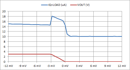
    I measured "Iq plus load current" for your circuit with a TLV2760 sample

    The blue line is supply current (in micro amperes) vs. input voltage. Red line is Vout in volts.

    The most interesting effect is that current drops when input overdrives output voltage to 0V.

    There is also a smaller supply current drop when input overdrives output voltage to 3V. 

    The highest supply current occurs when output voltage is between 0V and 3V. This is normal.

    If you want to leverage the supply current drop from running outside the linear mode, then design the circuit as a comparator.
    I can help if you are willing to change the design,.

  • Hi Ron,

    Thanks for the experiment. Now, I get to know the reason for higher current consumption in some PCBs.

    Also, when I remove the R3 and C2 in bad PCBs, the issue is solved. I am not able to understand the reason.

    Ron Michallick said:

    If you want to leverage the supply current drop from running outside the linear mode, then design the circuit as a comparator.

    I can help if you are willing to change the design,.

    Yes, I would like to improve the circuit. Please suggest.

    Additionally, I believe to try every possible way to get the existing circuit to work perfectly.

    Regards,

    Harish KS

  • Hi Harish,

    Ron had a question:

    "How much higher current are the units with higher ideal output voltage?"

    Can you please answer this question?

    When you remove R3 and C2, what issue exactly is solved? The higher output voltage or the higher supply current? And the improvement refers to what? The circuit in idle condition or in operation? Is the sensor connected then? Can you give us numbers?

    Please be much more specific.

    Kai
  • kai klaas69 said:
    "How much higher current are the units with higher ideal output voltage?"

    Can you please answer this question?

    It depends on the amplitude of voltage at output of TLV2761. From >20uA to 1mA. 

    kai klaas69 said:
    When you remove R3 and C2, what issue exactly is solved? The higher output voltage or the higher supply current? And the improvement refers to what? The circuit in idle condition or in operation? Is the sensor connected then? 

    The only issue I am facing is higher current consumption. The circuit is idle condition. In operation mode, i.e. TLV2761 consumes current as expected ~30uA.

    Regards,

    Harish KS

  • Former Member
    0 Former Member in reply to Harish Singh
    Hello Harish,

    I have a few follow ups for you:

    1. Can you please describe how and where, exactly, you are measuring the current.
    2. Is there any type of common-mode signal on the inputs? What kind of coupling is being used (AC vs DC)?
    3. What function do R3 and C2 serve?

    Regards,
    Daniel
  • Harish,

    1mA is far too high. That is completely unexpected. This would only happen if the parts got damaged.

    Because the desired output is a square wave, I switched the device to a TLV7011 comparator.

    TLV7011.TSC

  • Hi Ron,

    Thanks for the suggested circuit. TINA simulation is looking good.
    I will hard-wire the circuit and test it. If every thing went good, I will incorporate this circuit in my design.

    Thanks once again for the help.

    Regards,
    Harish KS