This thread has been locked.

If you have a related question, please click the "Ask a related question" button in the top right corner. The newly created question will be automatically linked to this question.

OPA657: Multi gain stage transimpedance amplifier using analog switches

Part Number: OPA657
Other Parts Discussed in Thread: OPA859, OPA858

Hi everybody,

I am trying to design a selectable gain stage using the OPA657 and an analog switch.

I want to have 5 gain stage and a wide bandewitdh (up to 20MHz).

But, the cds capacitance of the analog switch decreases the performances of the system.

I read this paper : but it may be difficult to implement with 5 gain stages.

Do anybody have a solution to handle the problem of the CDS capacitance of the switch?

Best Regards.

  • Hi Yohann,

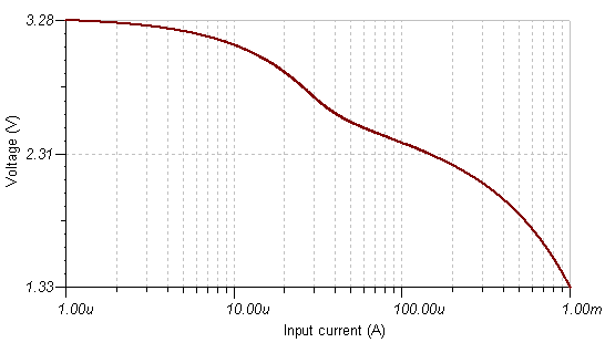
    What is your maximum gain at 20MHz? Using parallel switches is a good idea. Alternatively you can put low capacitance Schottky diodes in series across the feedback resistor to have a continuously variable gain, as long as you use a unity gain stable TIA like the OPA859.

    Best regards,

    Sean
  • Hi Yohann,

    quite honestly, fiddling with analog switches in the feedback loop of a decompensated 1.6GHz Opamp with a specified minimum gain of 7 is about the last thing I would do. :-) 1.6GHz is a frequency where even the series inductances and stray capacitances of SMD components play a dominant role. The layout example in section 11.2 of datasheet demonstrates how critical the layout is. Even fractions of a millimeter count. I think it's entirely impossible to integrate a handful of analog switches into the feedback loop of an OPA657.

    Also: The noise advantage of a switched gain TIA is only academic in this frequency range. There's so much noise leaking through the analog switches into the signal chain that the noise level could even rise with all these analog switches. And then the charge injection during the switchings...

    Really, I wouldn't do that. I would configurate the TIA for the minimum transimpedance (=gain) and do all the gain switchings behind the TIA. This allows you to make an excellent layout for the TIA and to obtain optimum results.

    Kai
  • Hi everebody,

    The things is, I must be able to perform measurement between 6mA and 6µA.

    So I have, 5 gain stage, lke 100Ohm, 1kOhm, 10kOhm, 100kOhm and 1MOhm with an other gain stage of 10.

    Using a first TIA stage with a 100Ohm resistor migth not working with low input signal...

    I already implement the solution with analog switches but the overall bandwidth is limited because of the Cds capacitance of the switch.

    And it's not working for 100Ohm and 1kOhm  gain stages... The OPA657 oscillates.

  • Hi,
    It could be ok if I have a 20MHz bandwidth with a 10KOhm feedback resistor.
    Best regards,
    Yohann
  • Hi Yohann,

    what is the source of your current?

    Kai
  • Hi Kai,

    It's a photodiode with a 5pF capacitance.
  • Hi Yohann,

    An OPA858 will give you 200MHz of bandwidth with a 10k TIA gain resistor and a 5pF photodiode capacitance. It is designed to have fast overdrive recovery. You should use series resistors for gain and leave spaces for series feedback capacitors (to minimize parasitic capacitance) like we do in the OPA858EVM. If you are having saturation issues, you can look at the OPA859 with a clamp feedback diode. It will keep normal gain for low signals but switch to logarithmic gain for higher ones, keeping the output from saturating.

    Best regards,

    Sean

  • You could also try something like this

  • Hi Sean,

    How could I select the gain of the TIA?

    I am using analog switches because I need to be able to select the transimpedance gain.

  • Hi Yohann,

    you could use two or more photodiodes, each with an individual TIA, where the photodiodes receive different light intensities from the original measuring light: 100%, 10%, etc. To decrease the light intensity you could either mount optical filters in front of the photodiodes or you could decrease the light intensity by decreasing the radiated area of photodiode by using a cover with a small hole in it.

    Kai
  • Hi Yohann,

    Kai has lots of experience and makes a good point about avoiding switches due to charge spike injection. Why do you need to actively select the gain? Diodes will passively select the gain based on input magnitude.  

    Can you explain in more detail your input range and what you need to do with it once it is amplified?

    Best regards,

    Sean