This thread has been locked.

If you have a related question, please click the "Ask a related question" button in the top right corner. The newly created question will be automatically linked to this question.

XTR116: XTR116 usage with only one source

Part Number: XTR116
Other Parts Discussed in Thread: DAC121C085, XTR117, ISO1541

Hello,

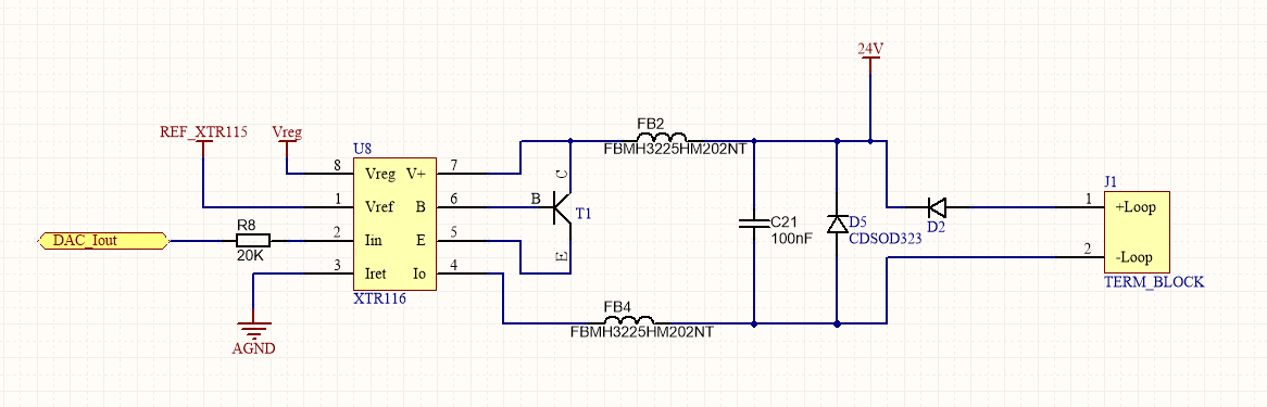
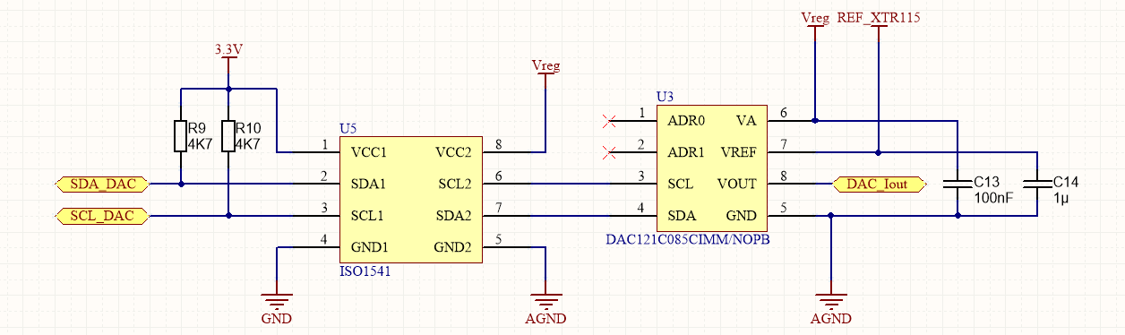
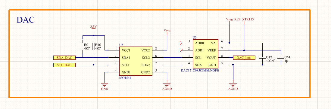
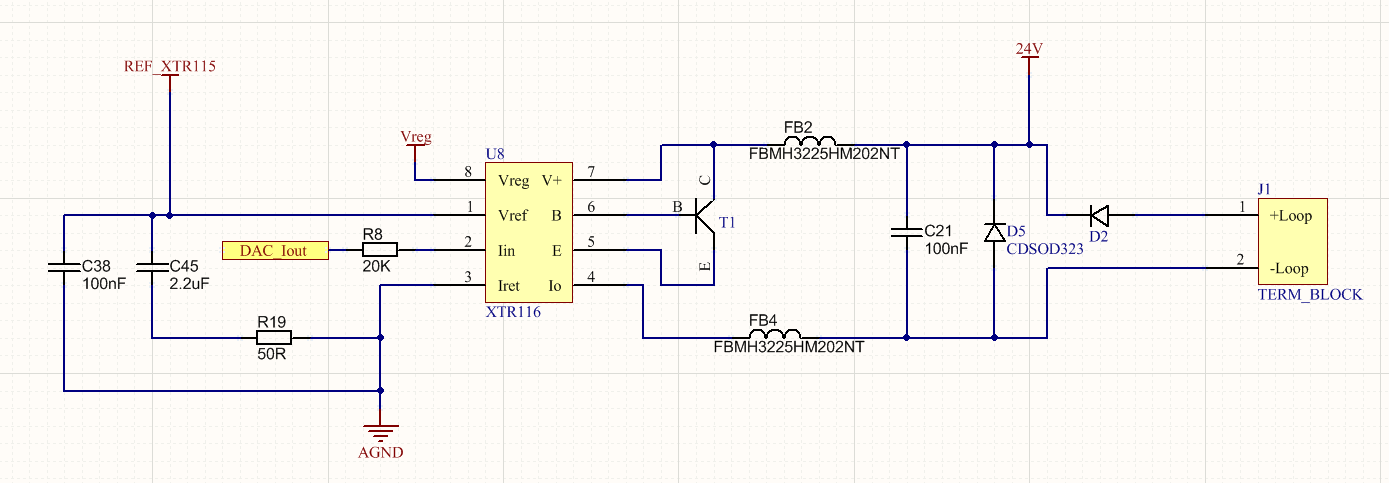
I am using XTR116 with DAC121C085. I have only one power source and 2 wires. Is that a normal operation ? +24V input for loop+ and loop- connected to that source's groudn through a resistor. There is converter which converts 24V to 5V and a ldo for 5v to 3.3V. Here my circuit.

  • Hi,

    The XTR116 is a 2-wire 4-20mA current loop transmitter. On 2-wire transmitters, the input circuitry and XTR117 floats with respect to the loop supply ground.  Essentially, the DAC GND pin and ISO1541 GND  pin should be connected to IRET, where the IRET potential is allowed to float above the 4-20mA loop ground.  Therefore, the 4-20mA  loop Ground and the IRET and should not be connected together. 

    See below example, the slide explains the effect of grounding IRET. on the left, the XTR117 circuit is working properly, where IRET floats (at 5.4V) working properly producing the ILOOP current.  On the right, IRET is grounded or shorter to the 4-20mA loop ground, and the XTR117 circuit is not working properly, and the device is unable to produce the ILOOP current output.

    Please also read the blog below on 2-wire transmitters.

    2-Wire 4-20mA – IRET Can’t connect to Vloop GND:
    https://e2e.ti.com/blogs_/b/precisionhub/archive/2014/12/09/part-2-two-wire-4-20-ma-transmitters-background-and-common-issues

    Please see attached presentation 2-wire and 3-wire transmitters. 

    1121.4-20mA_Basics.pdf

    Best Regards,

    Luis Chioye

  • So my circuit is correct ? ISO1541 isolating grounds so xtr116 is not connected to loop ground right ? AGND is only for DAC and XTR116. or should i remove the gnd from isolator and just connect the DAC's ground to I ret ?

  • Hello,

    If the IRET potential is allowed to float, where "AGND" is floating and not connected to the loop GND this will be correct.  

    The V+ pin shows a connection to +24V.  Is this a local separate +24V supply or is this just connected to the LOOP+?  The XTR116 should be powered from the loop supply (and not to a local supply).  If this only connected to the loop supply this is correct.

    Please  check the voltage reference XTR116 VREF compensation.  The datasheet recommends two possible compensation schemes on page 8, figure 5.   You could try the one in the bottom, then use CHF for the local DAC  VREF bypass.  Please see below.

    Many Thanks,

    Kind Regards,

    Luis

  • I cant understand you exactly. As i said i have only 2 wire and one power supply. 1 wire for 24V which is loop+ and it goes to V+ and a DC/DC converter so 24V can turn into 5V. then a ldo converts it to 3.3V. The other wire is loop- which connected to GROUND of power supply, through a resistor(250R). Please be sure you understand these first. There is and MCU and a sensor which connected to MCU. I want to commend DAC so it generates Voltage and with XTR116 that voltage converts to 4-20mA. This is what i want. if my circuit is wrong how can i fix it. You said so many things and i am confused. My board needs ground and power. Is this possible ?
  • Are you saying i can not use DC/DC converter 24V to 5V and use Vreg only instead ?
  • Hi,

    Since only a partial schematic is shown, I was asking where the '24V' node was connected to; since the '24V' net connector label in the schematic is shown once but it is not shown anywhere else on the partial schematic (the partial schematic does not show the DC-DC converter, nor the MCU connections). If you wish us to review, please provide the complete schematic.

    One thing you will need to change is the reference VREF compensation. Essentially you will use a 2.2uF bypass capacitor with a series RCOMP 50 Ohm across VREF and IRET on the XTR116 as shown on figure 5... Then you can use another local capacitor in the range of 100nF-500nF capacitor in close proximity to the VREF pin of the DAC121.

    Regards,

    Luis
  • I hope this is what you mean. I am going to order PCB for this.

  • Hi,

    in the first picture the burden resistance and its ground connection is missing. I guess the burden resistance goes to GND?

    With the added isolator ISO1541 the circuit should work now. But I would still add pull-up resistors at the SCL and SDA lines. Connect them to Vreg of XTR116. And use a proper power supply decoupling scheme for Vreg to filter out the i2C bus togglings.

    Kai
  • Thank you for everything.