Because of the Thanksgiving holiday in the U.S., TI E2E™ design support forum responses may be delayed from November 25 through December 2. Thank you for your patience.

This thread has been locked.

If you have a related question, please click the "Ask a related question" button in the top right corner. The newly created question will be automatically linked to this question.

PGA281EVM: Basic Gain Experiment, Inquiries on Power Supply and Desired Output

Part Number: PGA281EVM
Other Parts Discussed in Thread: ADS1259, PGA281

Hi I am an intern experimenting on the PGA281EVM to amplify a signal.

I am new to the board, so i followed the circuit diagram from SBOS664A less the ADS1259 ADC.

The current setup I am using is

VSP: +15V
GND: 0V
VSN: -15V

VDD: +3V

VSOP:+5V
VSON: 0V

I am using external sources for the power supplies.
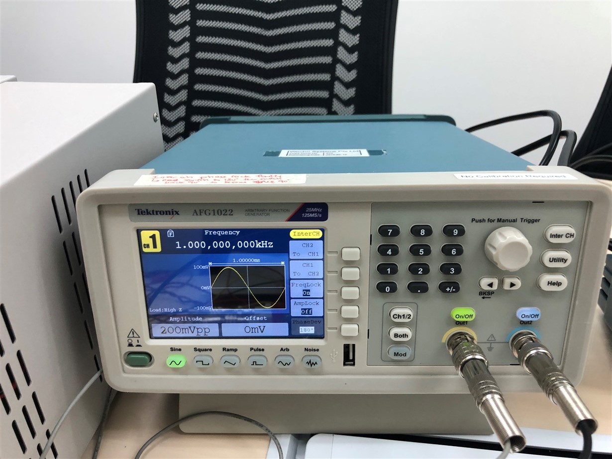
I have tested the gain using test input signals of  1Khz 200mVpp Sine Wave with 180 Degrees Phase Deviation.

The following are my observations 


1) If I turn on all the power supply, for the VSOP to reach 5V, i need to set the current  to 130mA. But then the differential output will not have any signals.
I have then lowered the current to 100mA, the V will be 4V, then i will be able to have an output.

The Range for VSOP is (+2.7V ~ 5.5V), so I am puzzled why  it is operating @  4V.

2)The output signal starts to be stagnant after a certain value of gain, causing the differential output to be different from the expected output.

May I know what would be the reason to cause this problem?

Differential Input

G3:G0

G4=0

Expected Output

Differential Output with VSOP @ 4V,100mA

400mVpp

0000

0.125

50mVpp

52mVpp

400mVpp

0001

0.25

100mVpp

100mVpp

400mVpp

0010

0.5

200mVpp

204mVpp

400mVpp

0011

1

400mVpp

400mVpp

400mVpp

0100

2

800mVpp

800mVpp

400mVpp

0101

4

1.6Vpp

1.5Vpp

400mVpp

0110

8

3.2Vpp

2.2Vpp

400mVpp

0111

16

6.4Vpp

2.6Vpp

400mVpp

1000

32

12.8Vpp

2.6Vpp

400mVpp

1001

64

25.6Vpp

2.6Vpp

400mVpp

1010

128

51.2Vpp

2.6Vpp


1011

RESERVED


1100

RESERVED


1101

RESERVED


1110

RESERVED


1111

RESERVED


Thank You.
  • Hi Jerron,

    Welcome to the Forum. A couple of questions:

    What voltage are you applying on the VOCM pin? The schematic shows VOCM is not connected. If you which to use VSON=0V and VSOP=5V supplies, please set VOCM to +2.5V. The VOCM pin sets the output common-mode voltage.

    Please confirm the common-mode voltage of the differential input signal.
    Both INN and INP need to be inside the allowed input range: (VSN)+2.5V < Input <(VSP)-2.5V.

    Many Thanks,

    Kind Regards,

    Luis Chioye
  • Thank you for the welcome and response.

    What voltage are you applying on the VOCM pin? The schematic shows VOCM is not connected. If you which to use VSON=0V and VSOP=5V supplies, please set VOCM to +2.5V. The VOCM pin sets the output common-mode voltage.

    I have left the VOCM pin open, and it measured to be 1.142V with respect to GND/VSON.
    Initially when i left it open, i am able to get an output signal for gain of 1,2 and 4(The table in orginial post).
    I have tried to supply VOCM with +2.5V, there isnt any output.


    Please confirm the common-mode voltage of the differential input signal. Both INN and INP need to be inside the allowed input range: (VSN)+2.5V < Input <(VSP)-2.5V.

    I am using a 1Khz Sine Wave, 200mVpp signals with 180 degrees phase deviation, so does it mean that the common-mode voltage of the differential input signal is 0? (V1+V2)/2
  • Hi Jerron,

    What function signal generator are you using, and can you please show how are you connecting the IIN and INP signals to the output of the function generator? How are you grounding the function generator with respect to the EVM GND? How are you measuring the outputs using an external meter?

    If you have a picture of the set up or diagram showing your input connections to the function generator, all the supply connections and the external meter connections as we could review.

    If you are set up using VSOP=+5V and VSON=0V; the VOCM needs to be set to +2.5V. The EVM evaluation kit already includes a 100kOhm voltage divider (please refer to resistors R3/R4 on the EVM schematic on page 3 of the user guide) that will set the voltage to VOCM =2.5V when VSOP = +5V; so when using the PGA281EVM evaluation board, there is no need to drive the VOCM pin.

    Something is not connected properly; or the device has been damaged. The expected quiescent current consumption for the PGA281 on the VSOP supply pin is only about ~1mA, so 130mA current consumption is excessive.

    Thanks and Regards,

    Luis

  • hi Luis,

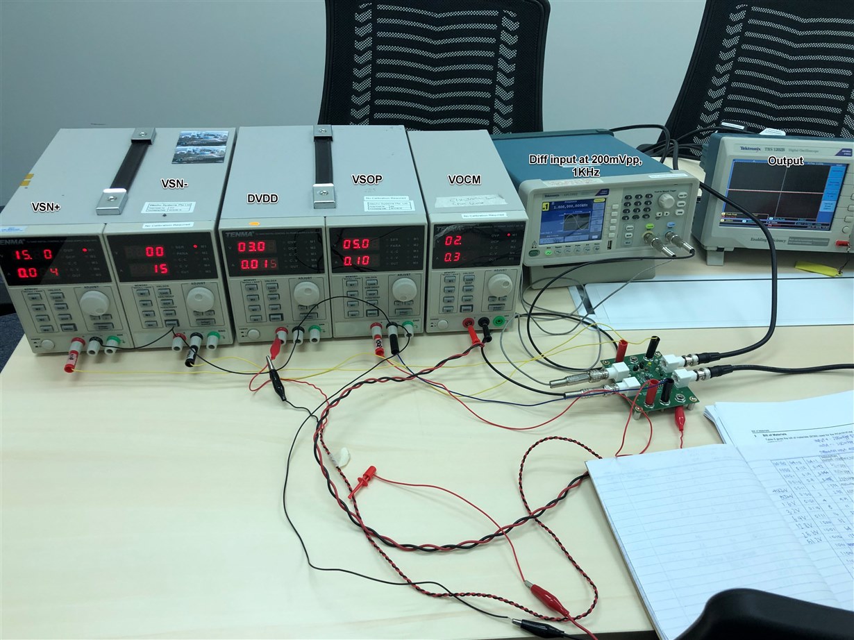
    I am the DFAE for this case. Visited them yesterday to discuss over the issue.

    Below is the setup: 

    One thing i observed is for VSOP source, they have use the ext power supply for this using the jumper setting. Will this caused any issue? 

    Here is the input diff signal:

  • Hello Luis,

    The equipments that I am using in this experiment are

    -Tektronix TBS1202B Digital Oscilloscope
    -Tektronix AFG1022 Arbitrary Function Generator
    -TENMA 72-10495 Digital-Control DC Power Supply 0-30V 5AX2

    Pictures and comments are in the link below.

    /cfs-file/__key/communityserver-discussions-components-files/14/Photos.pdf

    Thank You.

  • Hi Jerron,

    Thank you for the pictures of the set-up.  A couple of questions:

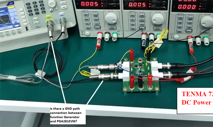
    1)  Are the cables used to connect to the IN+(J1) and IN-(J2) to the function generator provide a GND path to the PGA281EVM?  Looking at the picture, it is not clear if these are standard coaxial cables that provide a GND path.  (For example, the oscilloscope OUT+/OUT- connections show standard coaxial cables with a GND path connection).  If the input cables are missing a ground connection, please replace the IN+/IN- cables with coaxial cables similar to the ones you have used on the OUT+/- oscilloscope connectors that provide a GND path connection.  See picture below.

    2) As you have mentioned, when using an external VSOP supply, JMP1 needs to be set to EXT and if using external VDD supply JMP2 needs to be set to EXT. Can you confirm using an external meter the current on the VSOP supply?  If you measure ~100mA with an external meter, most likely the PGA281EVM is damaged.  

    Thanks and Regards,

    Luis

  • Heelo Luis,

    Yes those cable provides a GND path to the PGA281EVM, nevertheless i have tried replacing them with standard coaxial cables with a GND path connection.
    Both yield the same results.

    The Voltages on the Pins, Vdd measured has no difference with/ without JMP. However, the VSOP differs.


    INT

    EXT

    Without JMP

    5V from LDO

    5V from Power Supply

    With JMP

    5V

    It will force the +15V to 4.25V as the current set is 10mA.

    Depend on the current set, It will force +5V to 4V@100mA or 1.06V@10mA

    If there is no JMP attached, the VSOP pin(TP13) measured to be 0.156mA.

    With JMP attached, the current measured followed the power supply, which is 100mA.

    Thank You,

    Jerron

  • Hi Jerron,

    It appears that the PGA281EVM may be damaged.  I will contact you directly via email shortly.

    Thank you,

    Best Regards,

    Luis

  • hi Luis,

    I had request for new EVM via TI Singapore office early this week. Should arrive by end of the week to loan to Jerron to continue on evaluation. 

    Best rgds,

    kpk

  • Hi KPK,

    Thanks for letting me know; I have also contacted Jerron; and will continue the discussion via email

    Best Regards,

    Luis
  • hi Luis,

    Tested on the new EVM, test result work well. I ask end customer to monitor further. 

    Best Regards,

    kpk

  • Hi KPK,

    That's great news... Please feel free to post or open a new thread if you have additional PGA281 questions.

    Kind regards,
    Luis