This thread has been locked.

If you have a related question, please click the "Ask a related question" button in the top right corner. The newly created question will be automatically linked to this question.

TLV07: Protecting Op Amp Inputs

Part Number: TLV07

Hello,

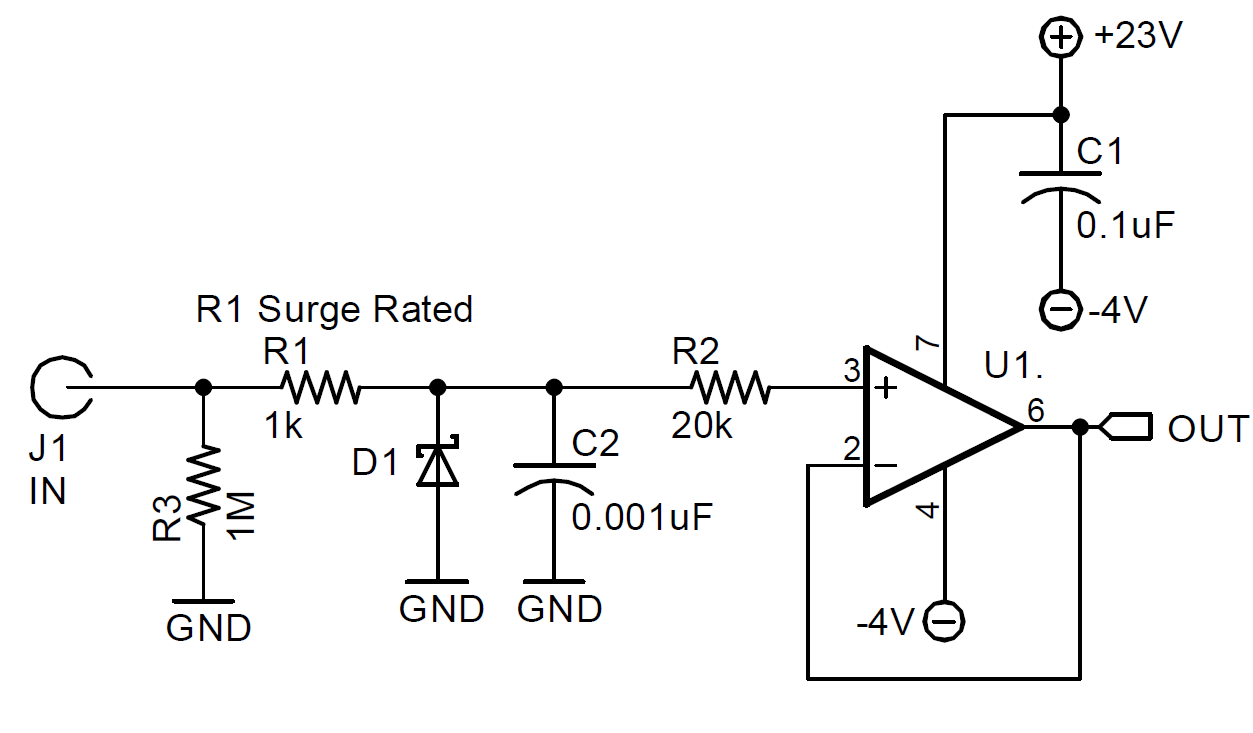
I am looking for advice in protecting the input pins on TLV07 op amp.  My design is intended to measure input signals from 0-20V and I've extended the power rails to -4V and +24V to ensure linearity throughout the measurement range.  But I want to protect the device from potential overvoltage to the non-inverting inputs as these are user accessible.  The main concern is voltage spikes, which we expect to be less than 100V, 100us but would prefer protection up to 350V.  This situation shouldn't be experienced without the op amp power rails applied, but I'd also like to understand the concern if voltage is applied to the input signal without actively driving the rails.

I understand in the Absolute maximum ratings there is issue as soon as signal input pin exceeds either rail by 0.5V.  I also see the maximum for signal input current is at 10mA.  Is protecting the device as simple as ensuring an overvotlage signal cannot exceed the 10mA current input limit?  (e.g. if we were to put a 1k resistor in line with the signal pin, it would limit current produced from a 350V potential to under 3mA).

I look forward to any advice and applications notes you can provide.

  • Hi,

    350V / 1k = 350mA in a worst case scenario. That's way too much...

    A good idea is to clamp the input voltage to the rails by the help of low leakage and low capacitance small signal diodes like the BAV99 or even BAV199. Limit the current through these diodes by a resistor which you put in front of theses diodes. Then insert another resistor between this clamping point and the +input of OPAmp. Limit this current to 10mA. If repeatedly currents are flowing into the TLV07 set the current limit to 1...2mA. Additionally mount a TVS to each supply rail to absorb these currents, as shown in figure 34 of datasheet.

    Kai
  • Thank you for your details Kai. I apologize for my typo there, I meant a 150k resistor, not 1k.

    With your advice to limit to <2mA, would putting a 200k resistor in-line allow safe operation for the TLV07? I understand this will generate some error due to the op-amp input's bias current, but I am okay with 200k * 3nA = 0.6mV error. I also am okay with >100us worth of delay so do not see an issue with the time constant. I assume with this solution I should still follow the suggestion of using TVS diodes on the power rails (assuming positive supply cannot sink and negative supply cannot source).

    I can also see how your idea of using two resistors with diode clamp inbetween would allow for much lower series resistance, and thus less error so I will keep this in consideration.

    Would either of these solutions also increase the ESD rating of the input pin? If not, would you suggest placing a TVS diode before or after the resistance to improve ESD immunity?
  • Hi,

    I would always use diode clamps to the rails, because this also helps to improve the ESD immunity. A resistor only can be a good solution, if the resistor is ESD rated and is large enough so that ESD cannot zap through the air from one terminal to the other and by this rendering the resistor "solution" entirely useless.

    Whether a TVS across the supply rails is necessary, depends on the overvoltages you expect. I think it's always a good idea to have them. A TVS at the signal input of OPAmp circuitry can also be helpful, of course, but the TVS usually comes with rather big parasitic capacitance and leakage current which must be carefully taken into consideration.

    For the diode clamp the BAV99 is a good choice. The BAV199 has even less leakage current but is less fast. If turn-on voltage is critical, a small signal Schottky diode like the BAT54 can be used. But a Schottky diode shows considerable more leakage current than the BAV99 and might not be a good choice in precision circuits demanding low leakage currents.

    An additional input filtering cap can also be very helpful. It can slow down the slew rate of overvoltage spike and give the diode clamp more time to turn-on. A cap can also absorb a big amount of the ESD charge.

    Kai

  • Thank you Kai.

    I will put in TVS diodes on both rails per your advice.

    If we use a TVS diode for surge suppression, this would clamp the input so is there any reason to use steering diodes in addition?  Note that I would be sure to use an ESD rated resistor before the TVS diode to protect the TVS diode, and a resistor between the TVS diode and op amp input to limit the input current.  (e.g. if our TVS clamps to 30V, using a 20k ensures 1.5mA).  Image attached for clarity.

  • Hi,

    yes, you can do this. Keep in mind, though, that during an ESD event (or another overvoltage condition) an overvoltage can develop at the TVS, which can be higher than the (static) turn-on voltage of TVS. So, you should provide enough headroom for the current limiting via R2.

    If your bandwidth demands are not too high, you could increase C2. This is also a very effective way to handle ESD: The larger C2 the more ESD charge can be absorbed.

    With your scheme above the diode clamps to the rails can be omitted.

    A good way to make R1 more immune to ESD is to use two or more identical resistors in series instead of only one.

    Kai

  • Thank you for your thorough responses Kai, your great advice is highly appreciated.