This thread has been locked.

If you have a related question, please click the "Ask a related question" button in the top right corner. The newly created question will be automatically linked to this question.

TLV4171: Output current and the maximum source impedance

Part Number: TLV4171
Other Parts Discussed in Thread: OPA2990, TLV2171, TLV9302, OPA2171, TINA-TI

Hello,

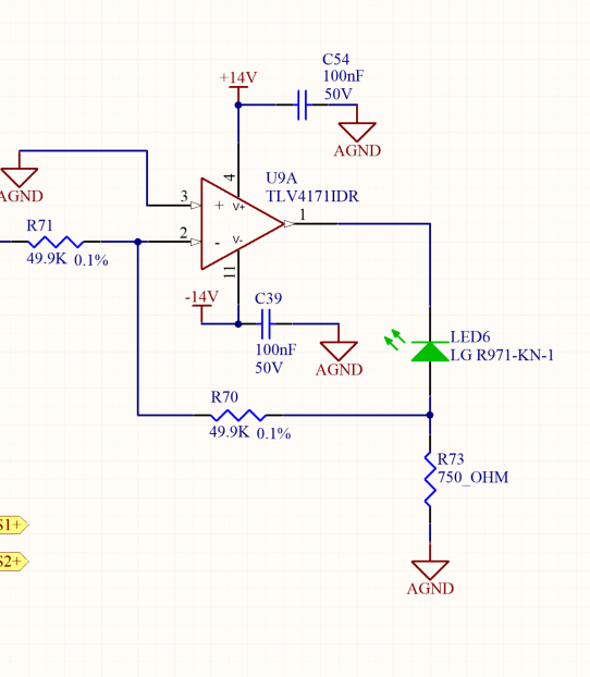
I'm trying to use TLV4171 in an inverting configuration to drive an LED. Following are my questions

1) Per datasheet, it says 25 mA is the ouput current, Is this specified for each individual op amp?

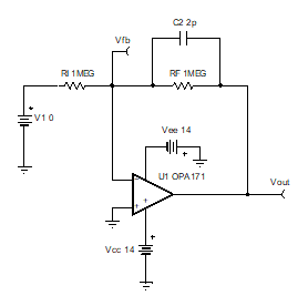
2) I intend to use 1 m ohm resistors for the inverting input and the feedback resistors, Is this okay? The reason being, the signal thats's coming as input to the op amp will also go to a DAQ in parallel and so I don't want to change the signal or have a voltage drop. To do this , I'm trying to isolate the signal from the op amp with 1 M ohm resistors.

3) What is the life time of this part? Will it be in production for next 5 or 10 years?

4) I also found another part TLV4171-Q1, per datasheet everything seems the same. Are there any performance differences between these 2 parts?

Please let me know.

Thanks,
Naveen.

  • Hello Naveen,

    1) The 25mA specification listed in the datasheet is the short circuit current limit which is the maximum current the device can output before the output collapses. To see the max output current for your required output voltage take a look at Figure 5 (Output voltage swing vs. output current) in the datasheet. And yes, this is for each channel of the device. However, operating at max output current for all 4 channels may cause the device to heat up above the absolute maximum ratings. Therefore, I recommend calculating the power dissipated by the device under your conditions. For more information on how to calculate the temperature the device may heat to I recommend watching our TI Precision Lab videos on Power and Temperature.

    2) Do you plan to use 1m ohm or 1M ohm resistors in the feedback (I assume "Mega" but just want to make sure). Either way there will be issues. Using 1m ohm resistors in the feedback will load down the output of the amplifier because the feedback components appear as load. So using 1m ohm resistors will appear as a 1m ohm load. Using 1M ohm resistors in the feedback will cause stability issues because the feedback components interact with the input capacitance of the device and create delay in the feedback. To counter the effects of the 1M ohm resistor and input capacitance interaction, you will need to add a capacitor in parallel to the 1M ohm resistor in the feedback.

    3) TI does not typically obsolete devices. However, in the case we do obsolete a device you can find our product obsolescence policy here.

    4) The difference between the Q1 (automotive) device and catalog device is that the Q1 device has met all standards required to become automotive qualified. However, I would like to point out that only the single channel TLVx171-q1 device is released and orderable online. The quad channel (TLV4171-q1) is not yet available.

    Thank you,

    Tim Claycomb

  • Thanks for quick response Tim.

    For question 1. Is there an alternate part that you can suggest with same specifications and price range but with a exposed pad package if possible? That way the heat dissipation can be managed better.

    Our system requirement is -/+14V supply voltage, output current of the op amp should be 25 mA atleast and it will be operating at an ambient of 55C normal used case, might be higher in some cases.

    For 2) Yes 1 mega ohms. The reason like I explained earlier is the input signal to the op amp shouldn't be affected from resistances.

    Below is the circuit I have, please suggest  the maximum resistance that can be used for R71 and R70 or a way to calculate them.

    Or if there is another way of isolating the input signal from the op amp.

    Naveen.

  • Hi Naveen,

    1) Does your design require a constant output current of 25mA? If so, I do not recommend using the TLV4171 in your design for the reasons stated in #1 of the previous post. Even if the device can dissipate the heat, the output current of the TLV4171 will not be able to meet the needs of your design.

    I recommend taking a look at the OPA2990. The OPA2990 has better specifications (especially output current) than the TLV4171 with a similar 1ku price. The down side of the OPA2990 is it is not currently released in a quad package (but it will be) and only has 1.25MHz of bandwidth compared to the 3MHz that the TLV4171 has. Do the specs of the OPA2990 meet your requirements?

    If you need or are interested in the quad channel version of the OPA2990 please private message me and we can discuss getting samples to you of the quad channel device once they are available.

    2) There really isn't a limit/maximum resistance you have to use. If you use a very large resistor in the feedback you will need to add a feedback capacitor to stabilize the amplifier. If you can't or don't want to use a capacitor in the feedback then I can help you determine what is the max resistor size. But I will need to know which device you would like to use before I can help properly size the resistors and capacitor (if you use one).

    Thank you,

    Tim Claycomb

  • Tim,

    The op amp ouput will be about 12 mA when the incoming signal is 10V(0-10V Analog input), that's the maximum current to drive the LED. So I don't have a specific need for 25 mA continous output, I just need some headroom above my maximum required current. That's the reason I chose this Op amp. However if I use the quad package , it's getting hot( from the PD calculations) since I have to drive 4 LED's. So I decided I will use TLV2171, the dual channel op amp.

    As for the resistor size , I would appreciate your input. So, the circuit is all the same and even the op amp is the same.
  • Hi Naveen,

    Another device to consider which has better specs (other than bandwidth) than the TLV2171 is the TLV9302. You will also have more output current headroom with the TLV9302. The 1ku pricing online of the TLV9302 is $0.30 compared to $0.43-$0.50 (depending on package) of the TLV2171. Would the TLV9302 work better for your design?

    Thank you,

    Tim Claycomb

  • Tim,

    I went through the datasheet and it certainly looks better in some aspects.
    We've a requirement of IC's with 4 KV ESD HBM Rating. This seems to have 2 KV rating.

    Do you think the headroom that I have in TLV2171 is not enough if my maximum current is 12 mA? Please let me know if that's a problem.
    If that's the case I will go with the TLV9302 since I've limited options. It has the same package available and the pin out is the same. I can change it any time with a Bill of material change.

    Coming back to the resistors, whether I use TLV9302 or TLV2171 would it make any difference if I want to 1 M ohms.
  • Hi Naveen,

    I believe you have enough headroom with the TLV2171. I recommended the TLV9302 because it has better specs and it has a lower 1ku price.

    If you use the TLV9302 or TLV2171 you will still need a cap in the feedback if 1M ohm resistors are used or you will need to reduce the resistor values. I'll work on getting you the largest recommend resistors to use in the feedback and what feedback cap to use if you do use 1M ohm resistors. One additional down side of using 1M ohm resistors in the feedback is that it will add more noise to the system. Please see our TI Precision Lab videos on Noise for more information.

    Thank you,

    Tim Claycomb

  • Thanks Tim. I'm looking forward for the suggestions.
  • Hi Naveen,

    For the OPA2171 I do not recommend using gain setting resistors greater than 33kohms in your inverting gain of -1V/V (Noise gain of 2V/V) circuit without a feedback capacitor. Using 33kohms in the feedback sets the zero frequency in the 1/Beta curve at ~1.6MHz which is just outside the bandwidth of the device when in a noise gain of 2V/V. For a more robust design I would use a resistor value less than 25k to account for passive tolerance values and variation in device bandwidth. The 1/Beta frequency is calculated using 1/(2*pi*f*Cin) where Cin is the equivalent input capacitance of the device (different capacitance + common mode capacitance). Please see below for a TINA-TI stability simulation of your circuit. I have also attached the TINA file if you would like to run the simulations yourself.

    If you would like to use 1M ohm resistors in the feedback you will need to add a feedback capacitor of at least 2pF to compensate for the zero in the 1/Beta created by the 1Mohm feedback resistors and the input capacitance. Please see below for the schematic and simulation results.

    I recommend watching out TI Precision Lab videos on op amp stability for more information.

    OPA171 Feedback Resistors.TSC

    Thank you,

    Tim Claycomb