Other Parts Discussed in Thread: INA122
First of all I would like to say that I am not very technically apt with electronics but I am attempting to complete a design project that involves amplifying signal from a strain gauge Wheatstone bridge. I have soldered up 3 INA125 chips onto PCB boards identically and they are all giving me wildly different voltage outputs. Also, I should note that I am using the single supply wiring depicted in figure 6 of the datasheet.
One of the three circuits gives me the desired 2.5V drop. One is reading a drop of 0.75V. The last is reading a drop of 1.75V, respectively. I have no idea why this is happening and could use some assistance in figuring it out. I have walked around to every pin on each of the three chips and they are all being supplied with the intended amount of voltage. The only pin that varies in the 10/11 output pin.
Some more information about my circuit:
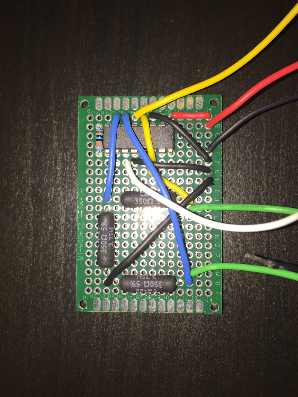
I am using 350 Ohm strain gauges/resistors in the bridge. Also, my gain resistor is 330 Ohms.
Could my soldering attempts be burning up the chips? Or are these chip especially susceptible to static damage? I am baffled why this is happening and am running out of troubleshooting ideas.
Thank you in advance...