This thread has been locked.

If you have a related question, please click the "Ask a related question" button in the top right corner. The newly created question will be automatically linked to this question.

LMP7721: Non linearity on the amplifier

Part Number: LMP7721
Other Parts Discussed in Thread: LM7705

Hi,

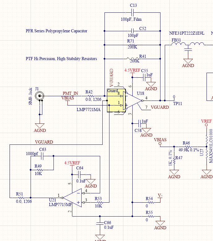
I have a "linearity" issue with the LMP7721MA. \

I have observed non-linearity at the low end of the amplifier circuit?

    1. Is there a high pass filter that is cutting off the response? 
    2. Is there a tolerance stack up in the components in the amplifier circuit that is relevant at the low end of the current spectrum, i.e. +/- 50pA might be inconsequential at a measurement level of 10^-9, but very significant at 10^-10 and beyond.

Regards

Ravi

  • Ravitej

    Could you provide a schematic and a scope photo of the nonlinearity your seeing?

    Regards
    Dennis
  • Dennis

    See circuit above. I do not have a scope reading, but I have some values in a table. The source is a pico-amp current source.

  • Hi Revitej, seems like a lot of transimpedance stuff these days - I am sure Dennis will asks the same things, but

    1. What is the value for Vref , probably want a cap across r47 to knock down the resistor noise - value would depend on your signal BW requirements.
    2. What is the total C on the PMT_In Line, that partly sets the response shape. And I am sure you have that fine now seeing this looks like a production test data set.
    3. THe LMP7721 needs about a 0.1V headroom on the negative side at the output  - which is why Vref hopefully is at least that - or that could be your linearity issue.
    4. I am interpreting your tables as a test current input - hopefully that Keithley has a low source C?

  • Hi Michael,

    1. Vref = 2.5V
    2. The data set is not for production. It was for my understanding , at what level of concentration do we start observing non-llinearity. It is not the case with every circuit. Some circuits as you see are behaving perfectly fine. the inline C is around 2nF within the circuit , but I am not sure if that's the right value.
    3. Absolute voltage reading at pin 4 of LMP7721 is about 0.3V. This is when there is no aerosol concentration.
    4.I use a Keithley 6220 current source input tolerance of ±0.05 amperes .

    Regards

    Ravi
  • Hi Revitej,

    So I guess what I meant to ask of Vbias value is about 0.3V - that should be in range.

    The inline C =2nF, that is at J1? Is that the PMT cap or a blocking cap. What we need is the total shunt C to ground on the inverting input.

    If I convert your red cells into what that meant in a misreading at the op amp output voltage with 100kohm transimpedance, those are pretty small voltages. While very good, the input offset voltage drift is not perfect - any chance those rows with non-linearity had a temperature shift showing up as an output offset shift converted to an apparent measurement error.
  • Michael,

    Vbias = 0.3V . That is correct.

    No temperature shifts. The data has been recoded in a temperature and humidity controlled environment.

    I would like to re correct myself, on the non -linear circuits , the Vo of the amplifier with respect to the Guard is negative comapared to the Vo of the linear amplifier circuit which is positive. So basically, to begin with, the amplifier has a -ve output voltage at the start which is causing non-linearity at the lower end of the spectrum.
  • yes, if the output is below say 100mV above the negative rail, there will be random non-linearity - did that answer your question? We sometimes use the LM7705 negative bias generator to swing the ground with good linearity.
  • Michael,

    Yes, I am also observing voltages 100mV below zero or even lower than that. I looked up the LM7705 and I believe it could help me in this situation. I will get back to you once I order a few and use them in the circuit to see if it makes a difference.