This thread has been locked.

If you have a related question, please click the "Ask a related question" button in the top right corner. The newly created question will be automatically linked to this question.

INA219: check register value

Part Number: INA219

Hi Sirs,

Sorry to bother you.

1.We would like to know how to how to verification INA219 read value, could you help explain it?

Actually we not sure the read value is correct.

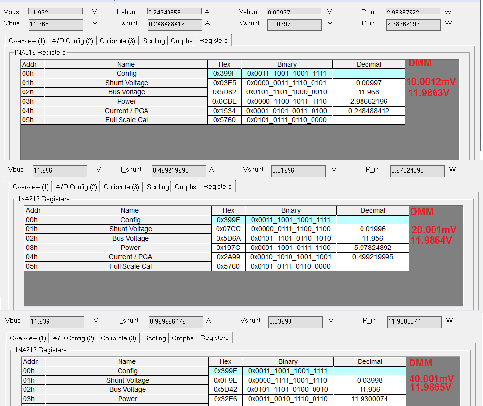
Currently is the following reading value (my high and low position is reversed, for example, 9f39 is actually 399f
Spec set  max load current is 1.5A, Vin+, Vin-pressure difference = 0.06V

root@OpenWrt:/# i2cget -f -y 0 0x40 0 w
0x9f39
root@OpenWrt:/# i2cget -f -y 0 0x40 1 w
0x4c19
root@OpenWrt:/# i2cget -f -y 0 0x40 2 w
0xeb58
root@OpenWrt:/# i2cget -f -y 0 0x40 3 w
0xcf48
root@OpenWrt:/# i2cget -f -y 0 0x40 4 w
0xff7f
root@OpenWrt:/# i2cget -f -y 0 0x40 5 w
0x6e57

2. We received INA219EVM, but looks not same as INA219 user guide? why? where can we would the big MB (Looks like TUSB73x0) information?

Thanks!!

  • Hi Sirs,

    Update our test as below

    I just adjusted the other load, the bus voltage is still 9V, and there are some possible reasons for the Current/power to read close but the voltage is wrong?

    In addition, I think the error is a little large. If 1.5amp load, should all measurement errors be 1.5*0.5%?

  • Hello Shu-Cheng,

    Thanks for considering to use Texas Instruments. There are a few items I need to clarify to answer your question. Is the value of your shunt 0.06V/1.5A =40mohm? Do you have any filtering between the shunt and the INA219? Both the shunt and filter resistors can contribute to the error you observe in your readings. Smaller tolerances minimize this error. Also the larger your filter resistors, the larger your gain error.

    As for your readings, you say that your current and power readings are close to what you expect while your voltage reading is not. Is this the bus voltage or the shunt voltage that gives you an incorrect reading? If you adjust your current to different values, do you consistently see current power readings that are close to what you expect? If adjusting the current does not dramatically change your accuracy, I would think there is an error in your code with respect to processing the voltage, because the power and current cannot be accurately calculated without the voltage values being correct.

    As for measurement errors, there will always be some amount due to input offset, gain error, CMRR, PSRR, and shunt tolerances. Typically input offset is the largest source of error and is found at the lower end of the measurement scale. As for the upper end of your measurement range, the gain error will dominate. Overall your measurement error should be decreasing with higher sensed currents.
  • Hi Sirs,

    Thanks for your reply.

    1.  May i know what voltage did you think we are read error? Shunt or Vbus?

    2. Why Vbus are only 9v, not close to 12v

    3. Our schematic as below, i not sure our shunt voltage is connect correct because we saw 219 is for high side. So could you help double confirm again?

  • Hi Sirs,

    Update as below

    Please help confirm the following questions, and provide test data, at 1amp load (input voltage 12V or so, including the actual voltage of the load voltage drop are marked as follows)
    Note for real measurement: Vshunt=Vin+-Vin- ; Vbus=Vout voltage ; P=Vout*Iout(max)

    (1) Vbus voltage error is too big. Where is the problem??
    (2)accrucy uses the current load or the maximum load set by cal to calculate the error
    (3) In the past, the current test data seems to have a large error. How to improve it? Is there still a need to adjust the SW register? Can the INA219 be more accurate or which side of the hardware needs to be adjusted?

  • Hello Shu-Cheng,

    Im including your questions with my answers below.  I think you may be omitting a step in your bus voltage calculation.  My measurements were collected with the INA219EVM and are below.

    1.  May i know what voltage did you think we are read error? Shunt or Vbus?

    Based on what you wrote originally it was not clear whether shunt voltage, bus voltage, or both were wrong. However, you said “Current/power read close” which should not possible if the voltage values are wrong, because current and power are calculated (not measured) from these values.

    2. Why Vbus are only 9v, not close to 12v

    This was not apparent from your first few posts, but I think you are making a calculation mistake.  In your first measurement in the last post, the bus register contains: 0x5bba, which becomes 0xB77 after 3 right bit shifts.  0xB77 corresponds to 2935 in decimal and if you multiply 4mV by that number, you get 11.74.

    3. Our schematic as below, i not sure our shunt voltage is connect correct because we saw 219 is for high side. So could you help double confirm again?

    INA219 has a common mode range up to 26V. As such a high-side implementation like yours should be fine.

    (1) Vbus voltage error is too big. Where is the problem??

    As I stated above, I think its a post-processing calculation issue.

    (2)accrucy uses the current load or the maximum load set by cal to calculate the error

    Accuracy is a byproduct of device specifications and the application measurement range.  Currents that are low micro-Amps and lower will yield a very large error, while currents that are in the mili-amp and Amp range should yield a considerably lower error.  Cal scales the current such that your max intended current is the max value in the current measurement register.  

    (3) In the past, the current test data seems to have a large error. How to improve it? Is there still a need to adjust the SW register? Can the INA219 be more accurate or which side of the hardware needs to be adjusted?

    You will need to show a specific example for me to answer this.

    Below are my measurements.  The red values are what I measured with a DMM.