This thread has been locked.

If you have a related question, please click the "Ask a related question" button in the top right corner. The newly created question will be automatically linked to this question.

LMC6062: LMC6062

Part Number: LMC6062
Other Parts Discussed in Thread: LM358,

Hello !
I am using the LM358 in a circuit for current measurement from 0 to 20mA and I am finding it very accurate the values ​​oscillate quite still with decoupling of 100nF and 10nF with low ESR.
I would like to know if I can replace it with LMC6062 which in my opinion will give me better precision. As for the power supply I am using a simple 5 VDC supply and with the gain my output voltage will be at most 2.5 Volts. Thank you!
  • Hi Leandro,

    can you show a schematic of your circuit?

    Kai
  • Hello !
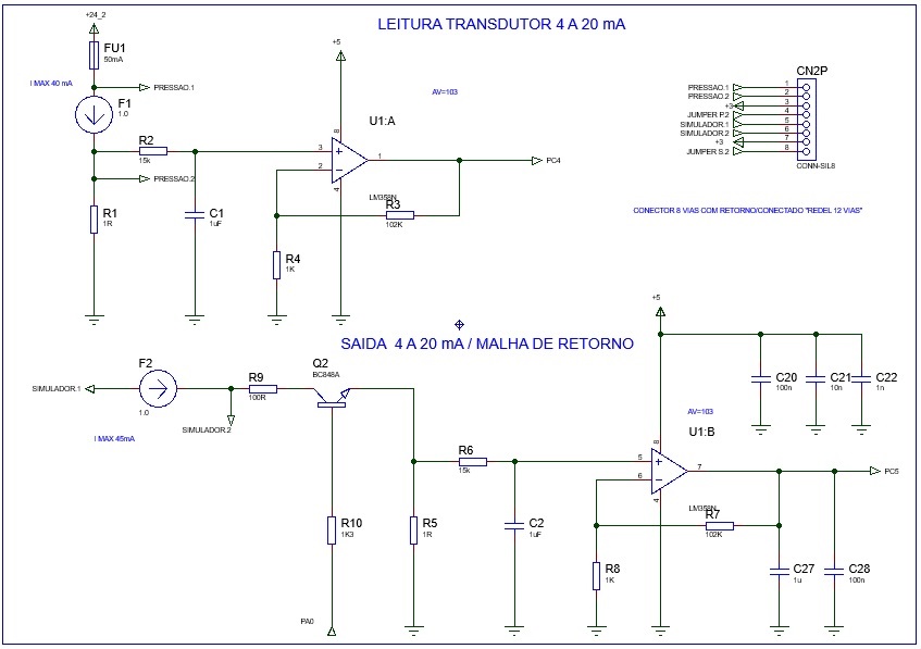
    Follow the circuit, the power supply of the LM358 and coming from a regulator 78m05.
  • Hi Leandro,

    remove C27 and C28 from the output of LM358! They will destabilize the LM358 by eroding its phase margin and will make the LM358 oscillate.

    Kai
  • OK, thank you very much, I will remove the capacitors, they were placed in the output because I believed that there could be noises in the Shunt R5 due to the PWM switching in the PA0 input, but the output A also fluctuates a lot and does not have the capacitors. After correcting this problem I would like to know if I can use the LMC6062 instead of the LM358.
    Is there any benefit in replacing it? I'm reading through a 12-bit AD with reference at 3.0 V which will give me just over 0.7 mV of resolution in the Read. And the more stable the amplification is the better for me.
  • Hi Leandro,

    it's true that the LMC6062 is much more precise (in terms of offset voltage, e.g.) than the LM358. But the LMC6062 is a micropower OPAmp and is much slower than the LM358. So, it depends on the ADC whether the LM358 can be replaced by a slower OPAmp. Some ADC (especially SAR ADC) have a short sampling time and the OPAmp must be fast enough to fully settle to the final value within this sampling time. If the OPAmp is not fast enough, the ADC will give wrong results.

    What ADC do you connect to the output of LM358?

    Kai
  • Many thanks for the clarifications!
    I actually use the SAR type, and I collect samples in very short periods with RTOS and save via DMA to calculate a circular mean.
    Perhaps the best option at this time is to stay with the LM358 and continue researching alternatives to future circuits. Many thanks again for the help kai klaas69 and is always good to rely on the experience instead of taking desperate actions.
  • You are welcome, Leandro.

    Feel free to contact us, if you need help finding an alternative for the LM358.

    Kai
  • Hello good Morning !
    I'm having more difficulties with this circuit.
    When I activate the pwm that supplied current to the circuit and provide the voltage signal that will read the B channel of lm358, the output signal of channel A goes up a lot. And I have a totally wrong reading, but when I do individually dont't have this problem .Please this type of configuration for AmpOp is functional for current reading of a transducer of 4 to 20mA?
    I am having several problems, I even thought of using a different configuration of the differential amplifier type to do these current readings and in the output where I am simulating the current that will be read in channel B use optic coupler for the drive and remove the current circulation of the board.
  • Hi Leandro,

    I do not fully understand what you are doing. Why is a PWM signal provided at PA0? What is its purpose? What is connected to "simulador1"? What is F1 and F2? Fuses? Why are R1 and R5 so low ohmic?

    Please elaborate a bit what your circuit is intended to do.

    Kai

  • Leandro

    We have not heard back from you so we will close this thread. Please reply if further discussion is needed.

    Regards
    Dennis