This thread has been locked.

If you have a related question, please click the "Ask a related question" button in the top right corner. The newly created question will be automatically linked to this question.

RTOS/INA223: INA223 Equation2 and Power Modes description

Part Number: INA223

Tool/software: TI-RTOS

Hi Sir

I have a question about INA223 Equation2(page16) is correct or not as below.

Because I saw Power Modes description (page17) are conflict with Equation2

Maybe correct equation2 is POWERgain=VOUT/(POWER)(R SHUNT), Is it right?

Thanks for your great support.


  • Hello Hugo,

    Welcome to the forum. We’re want to answer your questions to your content.

    I believe the equations are correct and non conflicting.

    When INA223 is in the power mode, in order to determine the actual power of the system you take voltage reading at VOUT and plug it into Equation 2. In the example calculation since Vsense=50A*1mOhm=5mV and VCM =12V, this makes VOUT=0.005*12*20 = 1.2V according to Equation 1 and Power gain factor equaling 20.

    The ADC will measure 1.2V at VOUT since the INA223 output mode is configured to Supply Power mode. The computer will have to determine that if VOUT is 1.2V, then the system power is calculated with Equation 2, where Power = 1.2V/(20*1mOhm) = 60W.

    Hope this helps.

    Sincerely,

    Peter Iliya

  • Hi Peter
    Thanks for your reply. I understand your description and means.
    But I still have a question on my application. Total parameters as below.

    Vcm=19V, I(max)=6.63A, Power=126W, Rshunt=5mOhms
    My register value is 0x66(OUT=10, GSV=01, GBV=10), we also had tried GBV=00 and 01
    But we always get VOUT=1.1V

    Since VOUT=(Vcm)(Vsense)(POWERgain) and I don't make sure what root cause it.
    Could you help to comment these case if you have any idea?


    Thanks for your great support.
  • Hello Hugo,


    I am worried that you may be saturating the output voltage when the amplifier is trying to display the power reading although this should not be a problem if VS=5V, GSB is 0.1V/V, and GSV is 128V/V.


    With your initial configuration register (0x66 à 0.1V/V GBV & 128V/V GSV) the POWERGAIN will become 4.267 according to Table 4. So if VCM = 19V, IMAX = 6.63A, and RSHUNT = 5mΩ, then VOUT according to Equation 1 will become:

    VOUT= 19V*6.63A*5mΩ*4.267 = 2.687V.


    But if GBV is changed to 01b (0.2 V/V), then POWERGAIN = 8.533 and thus

    VOUT= 19V*6.63A*5mΩ*8.533 = 5.37V.


    So this configuration would bring VOUT out of its linear range.


    Specific to this part is its internal analog scaling and thus the output voltage might not actually slam into the VS or GND rail when it is saturating. This is explained on page 14 of data, section “Output Range”. This could be why VOUT does not equal VS approximately with your configuration and gain setting. Normally for other basic amplifier devices and all amplifiers, if the input is too large, then VOUT will slam into its positive rail, but this is not the case for INA223. Reducing the bus or shunt voltage gain should position the VOUT into its linear range.


    I would double-check the gain settings for shunt and bus and also take several measurements over milliseconds. Could it be possible that you were saturating VOUT, adjusted the configuration register to correct scaling, and then recorded a couple VOUT measurements very quickly after? If this was the case, the VOUT might still have been trying to recover from its overload while you took measurements with correct gain scaling. You can see an overload recovery example in Figure 32.


    Could you also check the shunt voltage measurements directly before and after the power readings? There could be an issue with parasitic shunt resistance that is artificially increasing your sense voltage and thus increasing VOUT. Could the 1.1V Vout actually be indicative of the system power? Are you measuring VCM and load current while you are reading the INA223 power readings?


    Hope this clears everything up.

    Sincerely,

    Peter Iliya

  • Hi Peter

    Thank you. I had found root cause. It's load EC code timing issue cause it.

    And I have another queation now.

    Shunt Resistor: 5moh, Power Gain: 4.267, Max Power: 126W, INA223 Vout 2.68V,

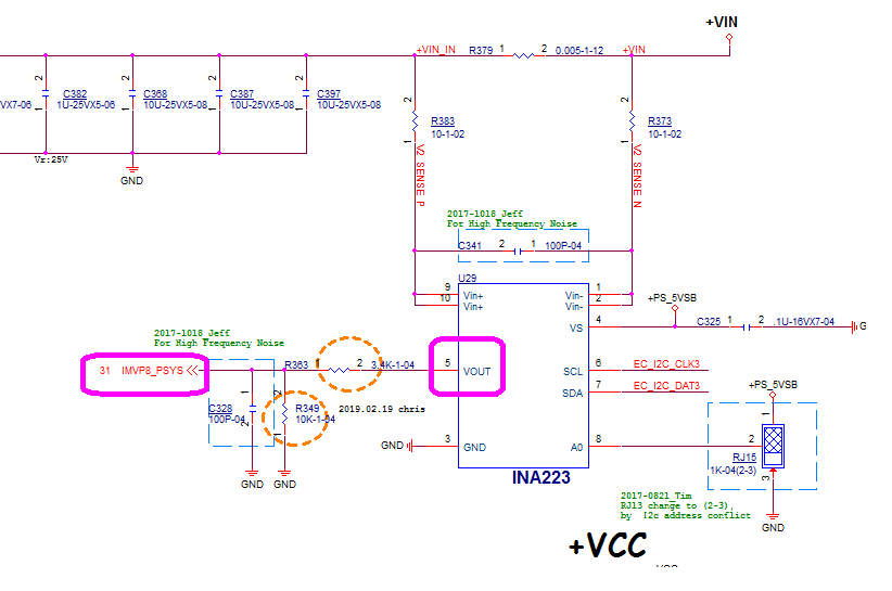
    Our schematics as below, Vout pin resistance division voltage(R363/R349) connect with IMVP8 PWM IC.(Since IMVP8_PSYS pin full scale is 2V)

    If R363/R349 be removed, all voltage behavior are normal.

    R363/R349 connected, We got INA223 Vout pin is 3.05V and IMVP8_PSYS is 1.1V.

    We had measure INA223 Vout pin to GND impedance is 249K when no power status,

    Could you help to check if there’s any design limitation regarding to voltage divider or Rshunt?

    Thanks for your great support.


  • Hey Hugo,

    Glad you're first problem was solved.

    So when R363/R349 are not populated, then you read correct VOUT. In this configuration are you measuring VOUT with a digital multi-meter (DMM) or with the ADC reading IMVP8_PSYS?

    When R363/R349 are populated and VOUT =3.05V, is this the correct VOUT first of all? If VOUT (measured at pin 5) is correct, but yet you measure 1.1V at IMVP8_PSYS something is wrong. When you are measuring 1.1V, is the ADC physically connected to IMVP8_PSYS? If so, then I think there could be some common-mode impedance inside the ADC that is adding a resistor in parallel to the 10kΩ. This would reduce the divisor from (10kΩ +3.4kΩ) to (<10k +3.4), which would raise what should be 0.77V to 1.1V.

    Please check the input impedance specs of the ADC and also the conversion times and bit resolution. If the ADC is SAR, there could be a chance that you are not properly setting up a charge-bucket RC filter for ADC. If you drive the ADC with a low-impedance output, such as a buffer, then you will probably remove the error you are seeing.

    You can learn with an example circuit (page 23) in our Analog Engineer’s Circuit Cookbook: Data Converters or from one of our presentations below:

    http://www.ti.com/lit/sl/slyy138a/slyy138a.pdf

    http://www.ti.com/lit/ml/slyp166/slyp166.pdf

    Sincerely,

    Peter Iliya