A related question is a question created from another question. When the related question is created, it will be automatically linked to the original question.
If you have a related question, please click the "Ask a related question" button in the top right corner. The newly created question will be automatically linked to this question.
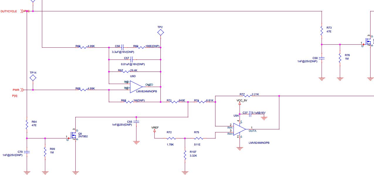
I suggest drawing this circuit on paper leaving out the DNP components. U9D is non-inverting (6.9 gain) for PWR signal and inverting (5.9 gain) for R66 signal. Q9 can force output of U9D stage to ground. so it chops the signal; DC to unipolar amplitude modulated. U9A is inverting , 0.325 gain and voltage on IN+ sets the offset voltage.
The duty cycle of the "DUTYCLCLE" input signal sets the duty cycle of the output signal.
The frequncy of the "DUTYCLCLE" input signal sets the frequency of the output signal.
The VOH of the output signal should be 86% of Vref voltage.
The VOL of the output signal is variable based on the first op amp voltage.