This thread has been locked.

If you have a related question, please click the "Ask a related question" button in the top right corner. The newly created question will be automatically linked to this question.

OPA547EVM: improved howland circuit

Part Number: OPA547EVM
Other Parts Discussed in Thread: OPA547, OPA548, OPA548EVM

Dear Thomas

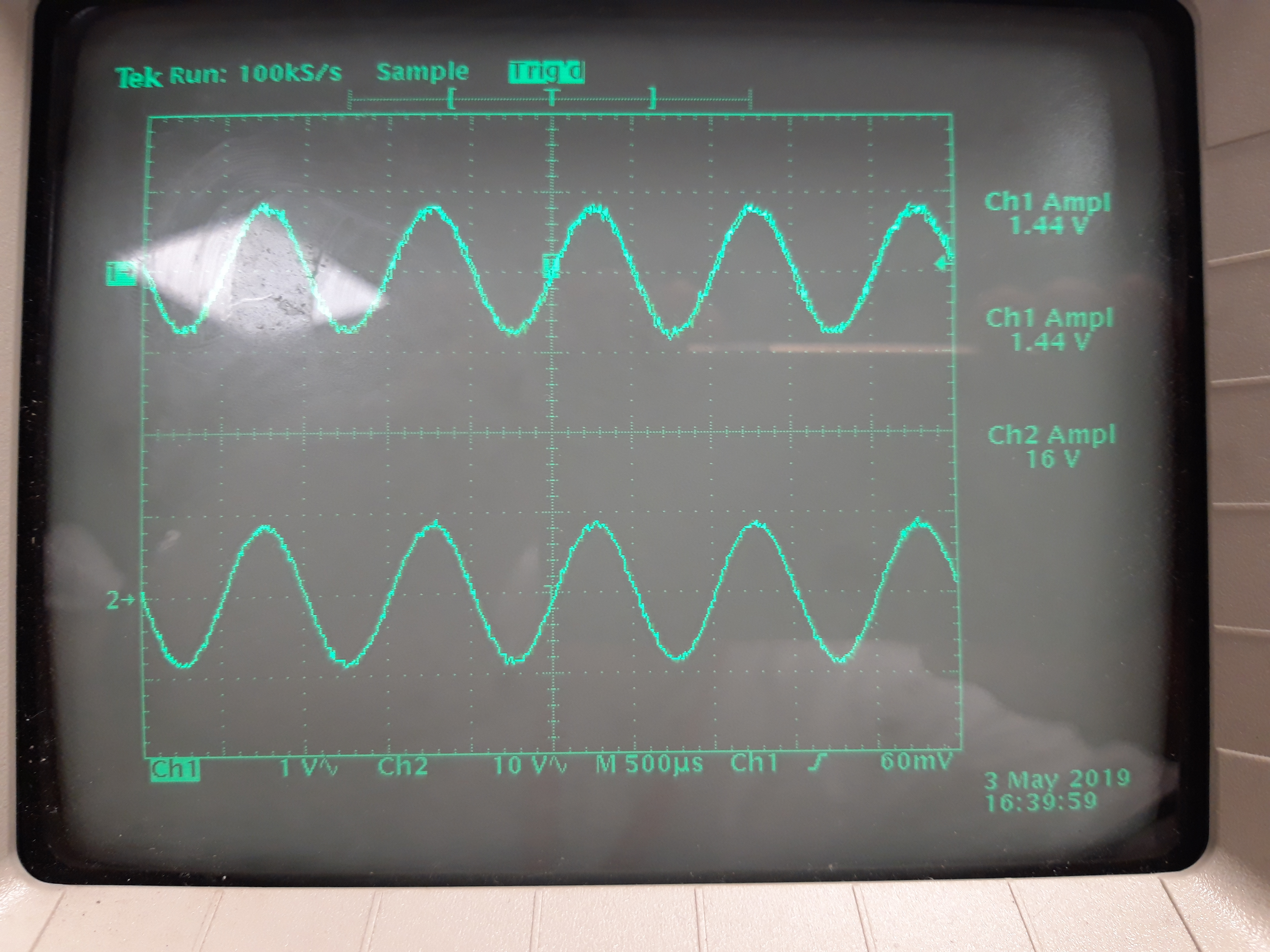
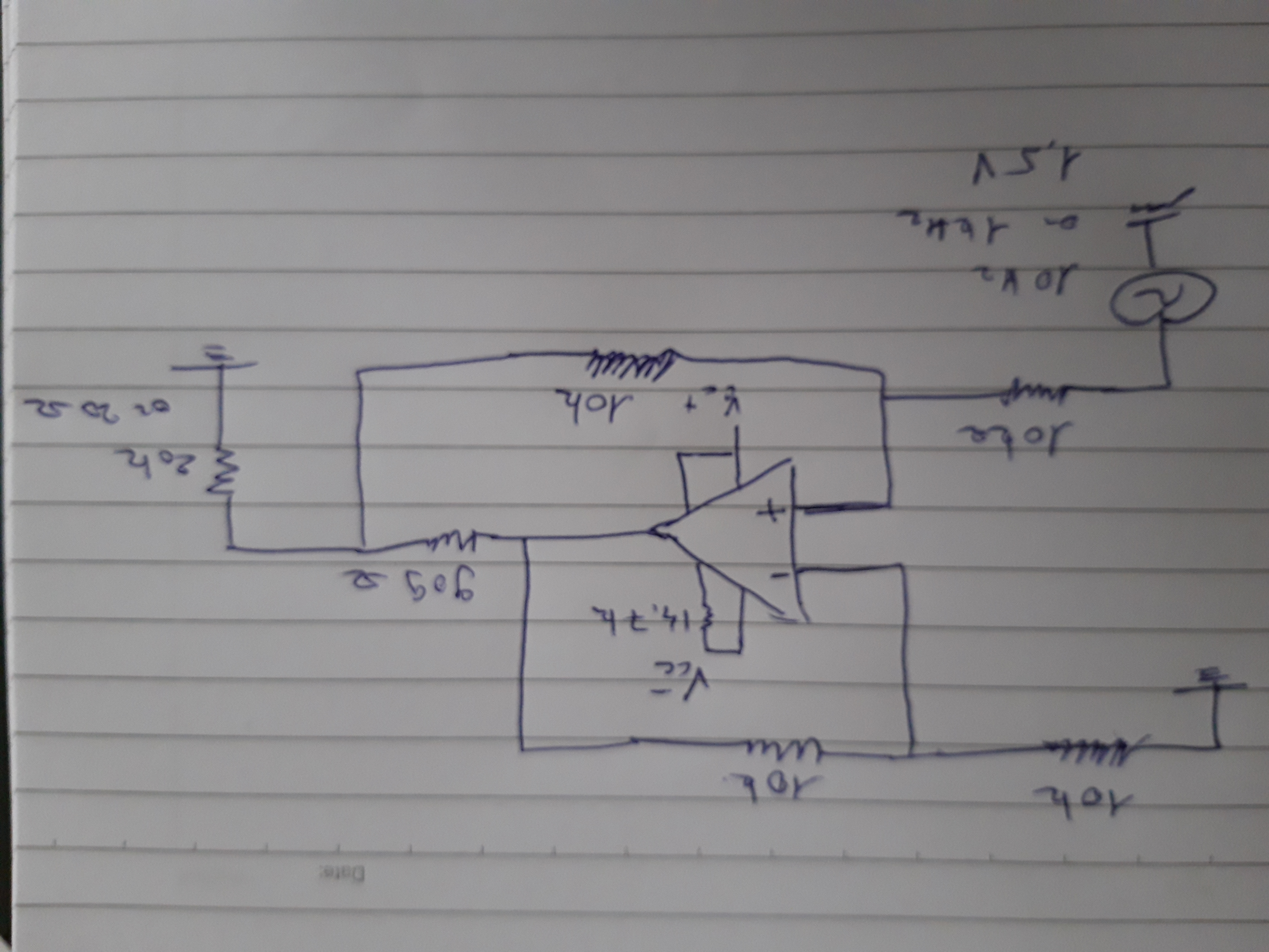
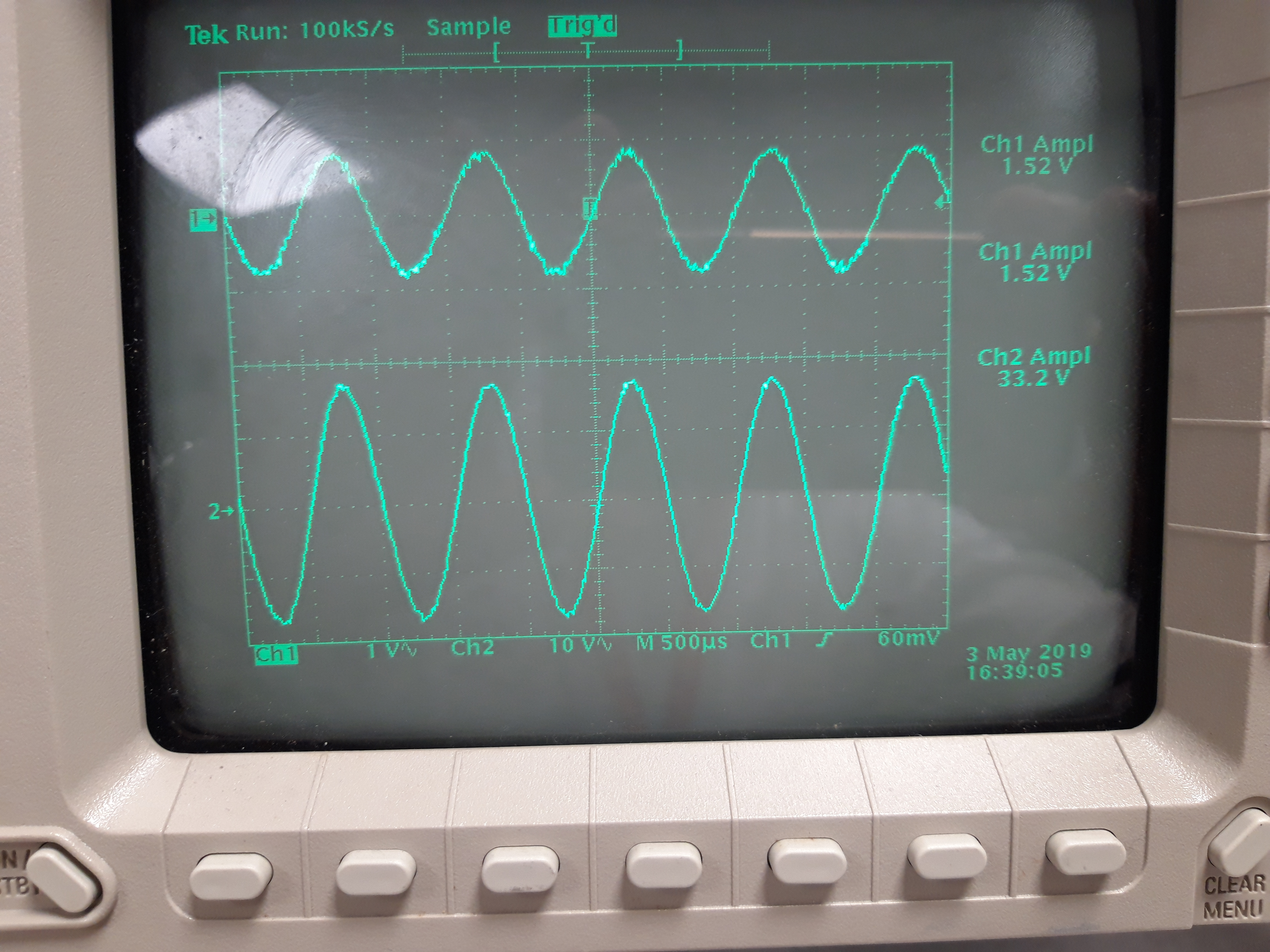
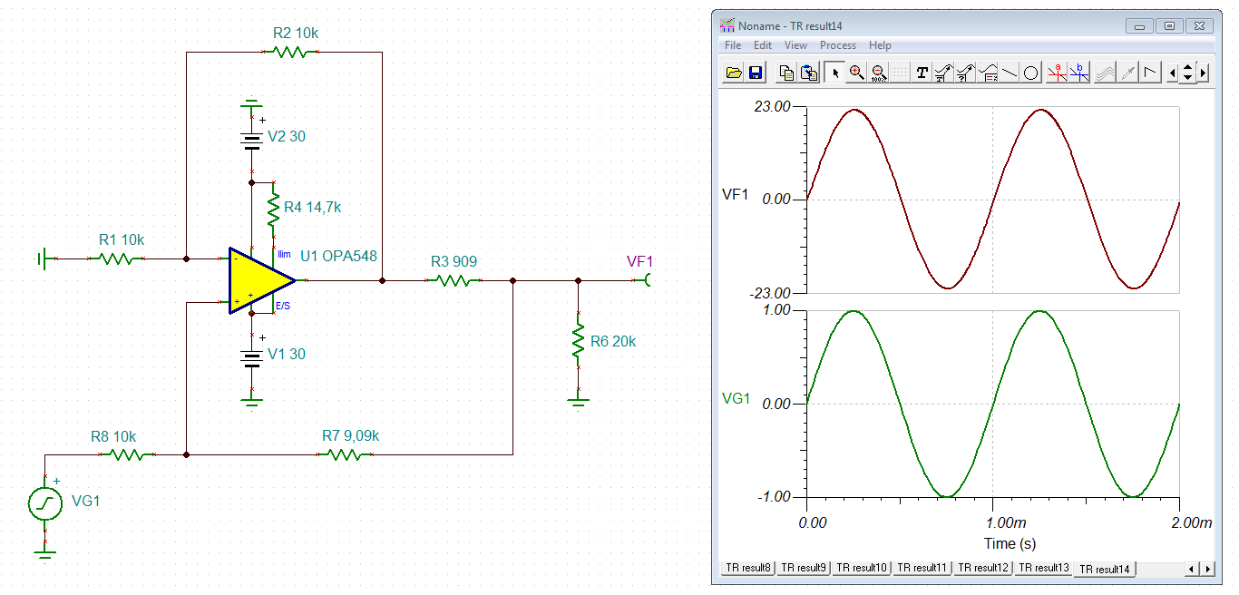
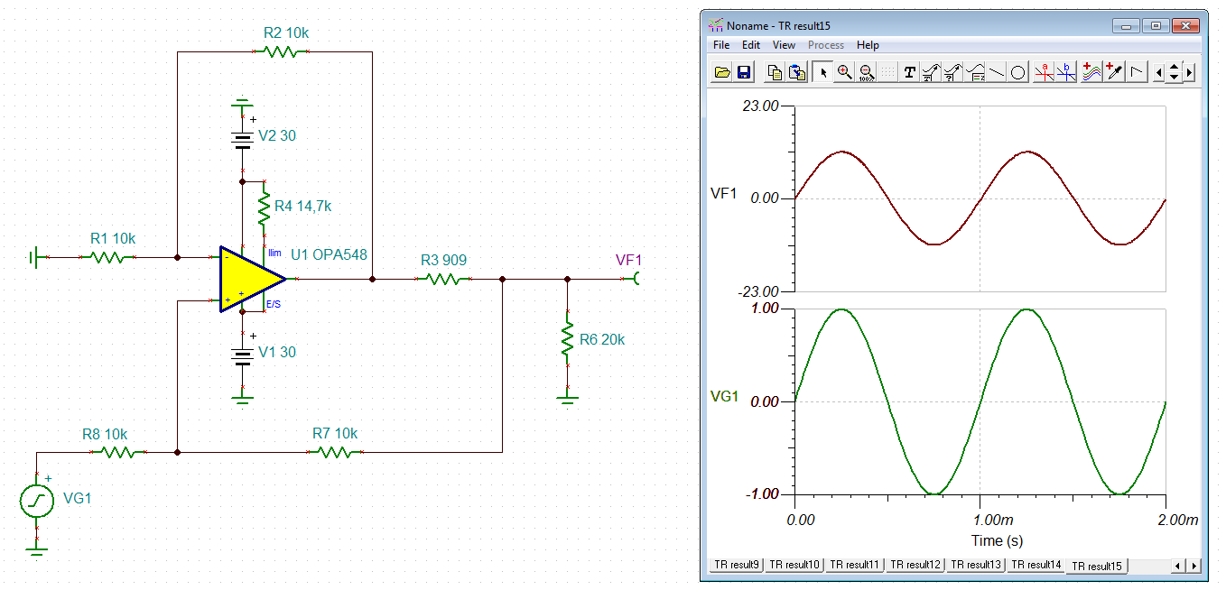
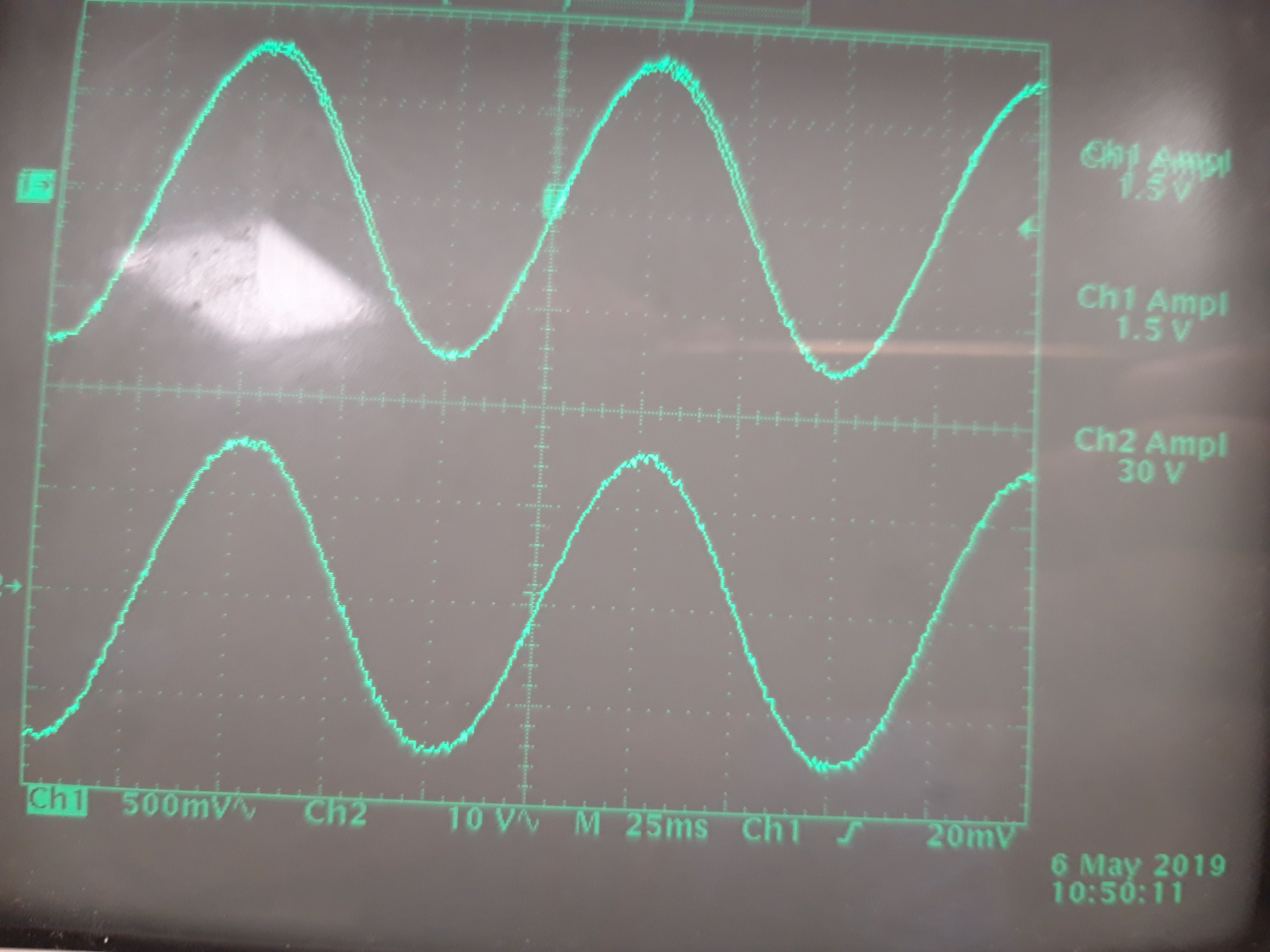
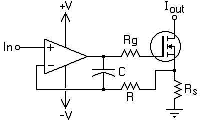
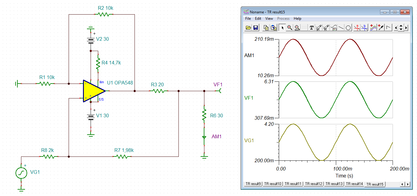
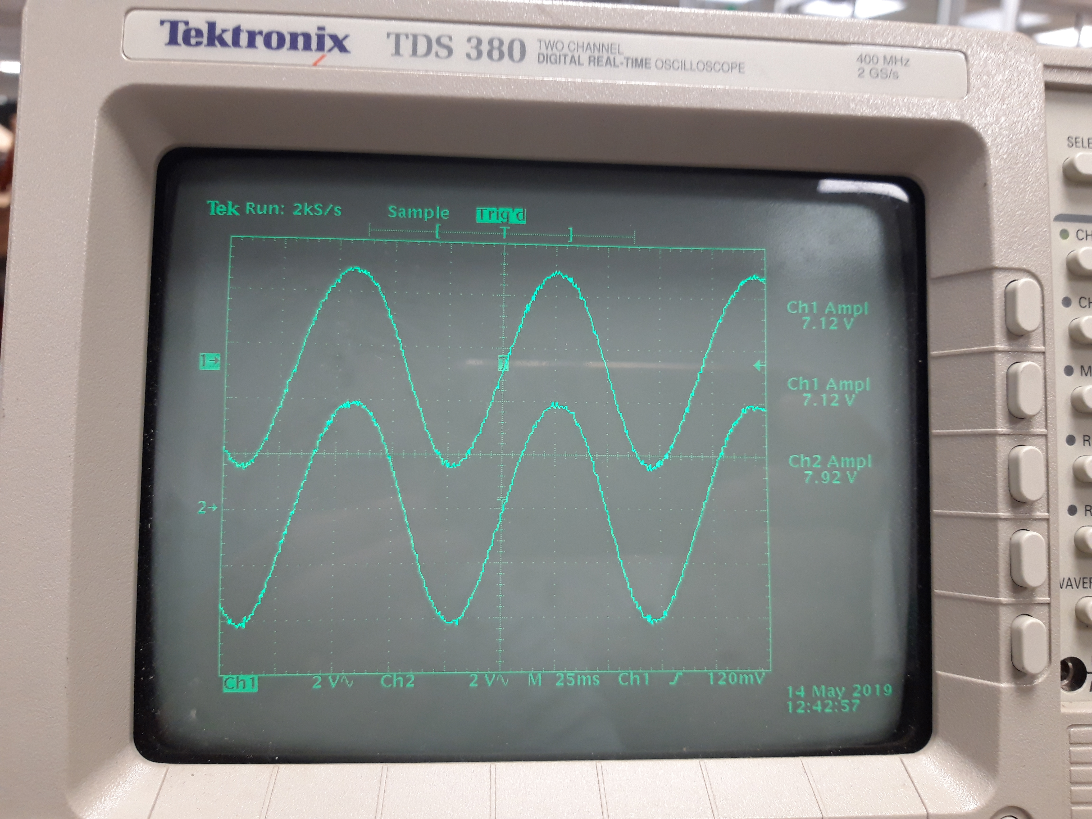
I used the OPA 548 to test the improved Howland circuit designed in figure 10 page 16 of the datasheet sbou132.pdf. using the same settings and resistance the output is about half of displayed roughly 16.4V instead of the 31.6 V proposed for the 20K load. if i disconnect the load and leave the output open i do get about 32V.  in addition my future device will be a few home microheater so i tested with a 20 ohms load, the output is just flat. do you have any recommendation so i can use this circuit with a small load (below 50ohms) and vary the ouptut current by tuning the input voltage from 0 to 0.5A up to 1A at most.

your feedback is very much appreciated..

Best regards

Ahmed

  • Hi Ahmed,

    have you noticed that RF+ must be 9k09 and not 909R? And that R7 must be removed?

    What are your supply voltages?

    Kai
  • Hi Ahmed,

    In retrospect, it would have been more useful if the OPA547/548 Improved Howland Current Pump example had been arranged for a much higher output current level. Nonetheless, the concepts are correct even at the very low current level used in the Figure 10 example.

    Can you provide us your circuit schematic showing component values, supplies, etc.? Also, show the load information and provide the needed output voltage compliance range that the pump is supposed to work across.

    Regards, Thomas
    Precision Amplifiers Applications Engineering

  • Dear Kai

    yes i did for RF+ i used 10k as i did not have a 9.09k at that moment but i dont think this is the critical point?

    for power supply i varied from +/- 20V to +/- 30V wtihtout load must  used 30V as you indeed get the 32V expected but it should have been with the load. i dont get it. attached the circuit without load and the traces. first trace is without load and second 20k.

    Thanks

    Ahmed

  •    Dear Thomas

    thanks for your feedback, i exactly reproduced the schematic fig 10. i attached a drawing with the values. for power supply i varied from +/- 20V to +/- 30V without load. without load i do get the 33.2V but drops half with 20k and 0 with 20ohm which i target.

    best Regards

     Ahmed

  • Hi Ahmed,

    RF+ must exactly be 9.09k, not 10k. That's the cause of your problems:

    ahmed.TSC

    By the way, don't omit the power supply decoupling caps. Put them close to the OPA548. And shorten the cables length and component wires.

    Kai

  • Hi Ahmed,

    do you know this appnote?

    snoa474a.pdf

    Kai

  • Dear Kai

    Thank you so much indeed the 9.09Ko is much more appropriate. i ve read the technical note i was wondering if reducing the resistance would help to get some signal if i use a 20-30ohms load since Iout is inversely proportional to R1.

    Regards

    Ahmed

  • Hi Ahmed,

    have you thought about using a standard MOSFET current sink instead of the improved Howland current pump?

    Kai

  • Hi Kai

    no i did not know this configuration but i am not sure it give the flexibility of a Howland circuit? I need an AC current flowing through my load this is why i went for the Howland but i havent check if anything better.

    i need to find a way to apply it to small loads, i tried with large parallel load but does not help.

    Thanks

    Ahmed

  • Hi Ahmed,

    what AC current shall flow though your load?

    Kai
  • Hi Kai

    My load is rather small it s a MEMS micro heater i need to heat with AC of less that 100 ohms typically 20-30 ohms. I need to pass low frequency < 10 Hz AC current varying from 10mA to say a maximum of  500 mA but if i get up to 150-200 mA i am happy with that. i try to put serial or parallel resistors to the load but it s not helping.

    Thanks

    Ahmed

  • Hi Ahmed,

    you mean like that?

    ahmed1.TSC

    Kai

  • Hi Kai

    thanks so much , if i read properly by injecting 4 V at about 7 Hz you get 200 mA on a 30 ohms load, correct? that sounds great , i am planning to vary current by steps of 20mA starting from 10 mA i wonder if the voltage source can go low enough. by the way i am trying to download the demo software to tune by myself, any how i ll try experimentally on Monday morning and give you feedback.

    thanks again

    Ahmed

  • Hi Kai

    I managed to open your file and run simulations. with an input of 250mV amplitude and without DC offset i manage to get 13 mA amplitude and up to 250 mA with 5V input at 1Hz. i will try experimentally Monday and give you feedback. out of curiosity how did you work out the resistance values? i looked at the application note 1515A and tried experimentally figure 5 page 6 but was far from expected.

    many thanks again

    Ahmed

  • Hi Ahmed,

    I played a bit with the values, keeping in mind that R3 + R7 = R8. It's no rocket science...

    Ok, now I see, you don't want to have a DC offset? Only a true AC current through the load?

    Kai
  • Hi Kai

    Correct, i want pure AC through the load to generate second harmonic. I tried on simulation without DC it seems working. I ll test the circuit asap.

    Thanks

    Ahmed

  • Hi Kai

    I tested your solution it works i just used 20 ohm as load to be closer to my device. it seems fine but the voltages necessary are higher than simulation by large.i can reach  240 mA at 11V  while for 4V as in the simulation i just reach 100 mA. The OpAmp heats up a lot and i had to add a heat sink to prevent thermal shutdown.one thing bothers me is the parasitic on the output signal just appeared today. overall it seems ok this way i can put that on a PCB. any recommendation welcome.

    Thanks

  • Hi Ahmed,

    the feedback resistances must exactly match the calculated values. So fine trimming of these resistors might help.

    Heating up of OPAmp is normal. You could reduce the supply voltages of OPA548 to a minimum.

    The scope plot shows an instability. Have you added power supply decoupling caps to the OPA548? Have you shortened the cables and component wires? Put a small capacitance in parallel to R2. This will improve the phase margin.

    Kai
  • Hi Kai

    yes i put 100nF decoupling caps to power supply, components are as close as possible to op Amp but i iwill try to shorten some wires and add a capacitance in parallel to R2.

    Thanks

    Ahmed

  • Hi Kai

    the output is much cleaner with a capacitance but surprisingly there was no effect when in parallel to R2 so i just decoupled the output and it seems decent to me, there is still some spikes but i feel it s the function generator that is poor, what you think.?

    Thanks

  • Hi Ahmed,

    it's difficult to get better results from a breadboard design. You would need a proper PCB to improve the results. You should even put the PCB into a shielding metal enclosure and use shielded cables.

    To make the Howland current pump circuit perfect one would have to know all the parasitic components (inductance, capacitance) of the MEMS heater and the whole setup (cabling!). With this data it would easily be possible to properly compensate the OPA548. Do you have an equivalent circuit model of the MEMS heater?

    Tim Green has made some remarkable stability analyses on the Howland current pump. You might want to search for them in this forum.

    Kai

  • Hi Kai

    the heater is a simple metal serpentin of about 20ohm nothing special so i guess can be model by R and L. I will sold all that on a PCB and have a go i just need to dissipate AC to another device the current design allow me up to 200 mA i am happy with that, i ll have a look at your reference to improve the setup. Thank you so much for your time and expertise really appreciated it.

    Best Regards

    Ahmed

  • Hi Kai

     the source is meant to supply on homemade microdevices my load resistance may vary upon nano fabrication. Do you think i could use potentiometers instead of fixed load to tune each time the set of resistances?

    Thanks

    Ahmed

  • Hi Ahmed,

    what do you want to tune? The load or the feedback resistances?

    The feedback resistances don't need a tuning, provided you are using 0.1% resistors.

    Kai
  • Hi Kai

    actually my load could be much higher than 20 ohms and i need to pass a wide range of current to dissipate different power each time. the problem is the design is set for 20 ohm ideally. Iwas planning to put all that on a PCB to fit into my setup but actually if it is valid on for one load better stay on breadboard to easily adapt. otherwise i need to design several set of circuits with components soldered but that s not effective as experimentally there could be several kohms of difference. TI sells the OPA548EVM but i ll face the same issue as the components must be replaced as well i might damage the circuit by soldering repetitively. that s why i was wondering if all resistances could be replaced by potentiometers?

    Thanks

    Ahmed

  • Hi Ahmed,

    I would use fixed resistors and rotary switches. And power-down the OPA548 before switching...

    Kai