


Other Parts Discussed in Thread: TLV3701
 Hello,
I am using TLV3701-Q1 as comparator circuit. Please find the circuit attached.
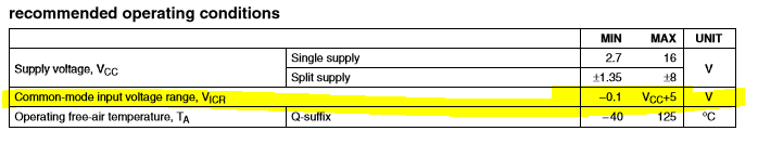
Here the 12V is from battery. So I have to consider reverse battery condition for this design. I have checked the TLV3701 datasheet for the input terminal voltage range capability.
It is stated that -0.1V to VCC+5V ( datasheet snapshot attached). So I wanted to test it directly.
Test Methode:
-------------------
1. Firstly checked the normal operation:
Inv terminal - 5.538V (after the divider and diode)
Non Inv terminal - 2.73V
Output - 0V
2. Reverse battery condition: (applied -12V over the 1Mohm resistor) (Expected damage but observed as below)
Inv terminal: - 0.511V (after the divider and diode)
Non Inv terminal - 0.5V
Output - 3.29V
Could anyone explain how it can happen? is there any internal structure (I couldn't find in datasheet).
Thanks in advance.
Thanks,
Sathish

