This thread has been locked.

If you have a related question, please click the "Ask a related question" button in the top right corner. The newly created question will be automatically linked to this question.

TINA/Spice/OPA454: Wein Bridge oscillator.

Part Number: OPA454
Other Parts Discussed in Thread: TINA-TI, , OPA743, OPA552, OPA452

Tool/software: TINA-TI or Spice Models

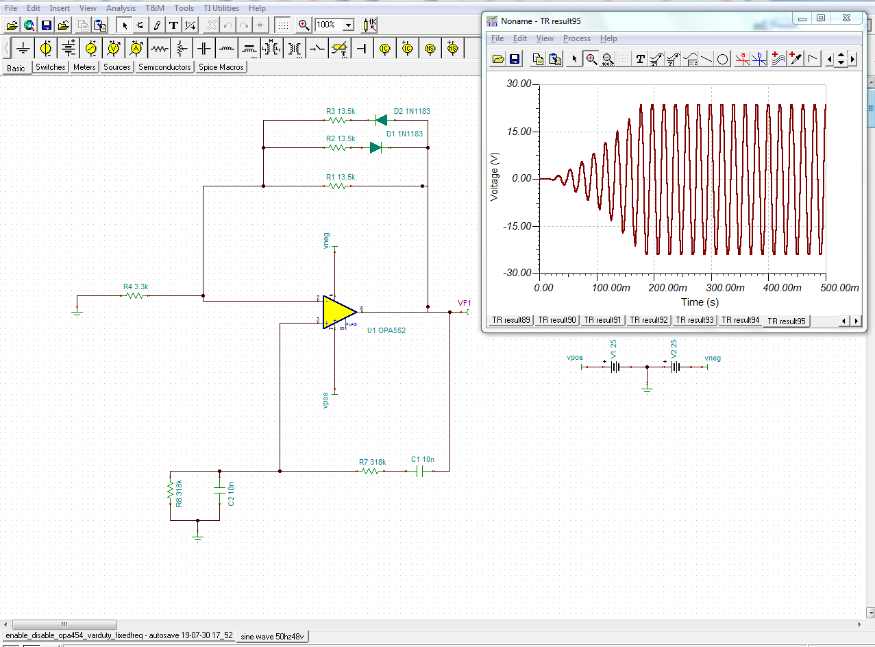
Hello, i am comparatively new to this analog part of the world and usualy deal with power supplies' designing for the embedded products. I have been working on generation of an oscillator. It needs to drive a capacitive load of around 20mA with 50Hz, 48Vpp ac signal. I just made a TINA simulation for the same using OPA743 as oscillator and then amplifying its output with OPA454. I got the waveform i needed. 

Out of curiosity, i tried to use OPA454 Directly to get a 48Vpp ac, but the output was even lower than opa743. Any inputs on this? 

  • .. I guess you talking about a Wien-Bridge oscillator ...

  • Hello Siddhesh,

    It is possible to get 48 Vp-p output from an OPA454 Wien-bridge oscillator. Note that it uses a combination of both negative and positive feedback. It is a matter of arriving upon the correct combination of closed-loop gain and resistances in the feedback clamping circuit. There are many possible combinations that will wok but since there are numerous variables it is may be difficult to realize the exact combination that gives the precise output amplitude. The gain is very sensitive and I iterated using TINA to find a combination of values that produces the approximate output amplitude. Note the circuit's slow start-up characteristics.

    Here's the TINA file in case you want to experiment with the circuit.

    OPA454_HV_Wien_bridge_01.TSC

    Regards, Thomas

    Precision Amplifiers Applications Engineering

  • Hi Thomas, 

    First of all a very heartfelt thank you for devoting your time to the query. 

    While the query was raised, I was busy simulating some circuits by myself. En route, I arrived at a circuit which gives me the required oscillations. The circuit utilizes opa552.  The settling time also seems a lot better. Though i have changed the op-amp ic, i think i will be going back to opa454 solely due to its enable/disable functionality. I Think that should not cause much difference though. i will simulate that circuit as well. 

    Also i will rig up the physical circuit and fine tune it as the capacitance of the capacitors will certainly vary on application of voltage and the circuit will oscillate at a frequency higher than designed for.

    I would be grateful if you could verify the design and comment on any improvements required. 

  • Hello Siddhesh,

    My simulation indicates that the OPA454 should be usable in the circuit you have simulated with the OPA452. As you have surely observed for this oscillator the gain must be carefully set to obtain the desired output amplitude. Also, I have noticed you decreased the supplies down to +/-25 V so the achieve a +/-24 Vpk output puts the OPA454 right at the maximum specified swing for a 1 mA output current. That may be an issue you have to consider.

    Here's the simulation result:

    Here's my TINA simulation file:

    OPA454_HV_Wien_bridge_02.TSC

    Regards, Thomas

    Precision Amplifiers Applications Engineering

  • Hello Thomas,

    Once again thank you for your time. My application will be a capacitive load with a requirement of 6mA. The datasheet for OPA454 mentions output current of 50mA. Also the output voltage vs output current graph in the datasheet ( snip attached below ), as per my understanding, shows there shouldn't be such issues as 48vpp would involve a swing from +24v to -24v. Please correct me if wrong. 

    Also i have tried simulation with OPA454. With some minor adjustments, i am getting the desired oscillations. Attached below is a screenshot for the same. 

  • Hello Siddhesh,

    OPA454 Figure 10 that you included shows how the output voltage capability lowers as the load current demanded increases. Just keep that in mind. Not only must the load attached directly to the OPA454 output be driven, but the feedback and input circuit path to ground be driven as well. So the peak load current may actually be higher than expected.

    Additionally, you show a 10 uF capacitor directly off the OPA454 output to ground. Op amps aren't often designed to drive such a large capacitance. Although the simulation does not indicate any oscillation other than what is expected, the huge load capacitance on the output might result in an unexpected oscillation condition. That certainly could happen if this were a straightforward Op amp amplifier circuit due to phase margin degradation. If the phase margin becomes zero the feedback becomes positive and oscillation takes place. Just make sure the circuit doesn't break into some unexpected oscillation mode.

    Regards, Thomas

    Precision Amplifiers Applications Engineering

  • Hello Thomas, 

    The actual load will be in range of few hundred nF. But yes, sure i will pay attention to your suggestions. I will procure a few ICs locally  and try to rig up the circuit to check if it works for me and come back to let you know the results. 

    Thank you,

    Siddhesh 

  • Hello Siddhesh,

    Okay, I hope all goes well with your bridge oscillator testing.

    If you can close this e2e now that would be appreciated. If you need more assistance later please feel free to open a new e2e inquiry at that time.

    Thanks, Thomas

    Precision Amplifiers Applications Engineering