This thread has been locked.

If you have a related question, please click the "Ask a related question" button in the top right corner. The newly created question will be automatically linked to this question.

OPA132: Simulating the PSRR of the OPA132 with Tina

Part Number: OPA132
Other Parts Discussed in Thread: OPA170, TINA-TI

Hi engineers,

I have a problem about using Tina to simulate an OPA's DC PSRR.

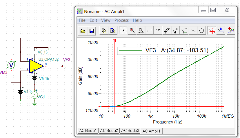
I learned the PSRR of OPA in the Precision Lab. Below is the result of the Tina simulation in the Precision Lab tutorial.

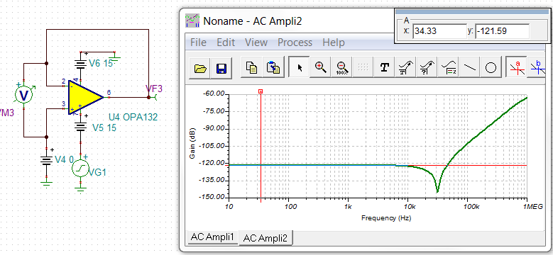
I also chose OPA132 and simulated it with Tina. Here are the circuits and results I took.

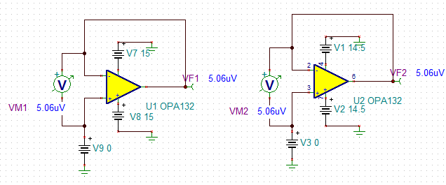
As you can see, the power supply was changed (a total of 1V changes), and Vos did not change, which is different from the tutorial results in the Precision Lab.

In addition, use the same circuit, but the op amp is replaced by OPA111, Vos still has no change. As shown below.

However, still use this circuit, the op amp is replaced with OPA170, the power supply changes, the op amp Vos changes.

Below is the DATASHEET of the op amp OPA170. It can be seen that the change in Vos is consistent with that described in DATASHEET.

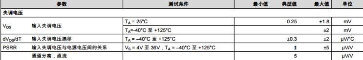
Therefore, it can be verified that the circuit taken should be no problem.

Why does the Tina simulation of the OPA132 in the Precision Lab get the correct results, and why does the Tina simulation I took not get the correct results?

  • Hello Wenyue, 

    Make sure you are using the latest updated models, the other way to do this is to just put an AC small signal on the supply, this looks pretty good, where PSRR is the negative of the gain curve, 

    So the model is producing 103dB as an input offset error term which goes down 6dB in this gain of 2 configuration to the output. Looks really close to the data sheet curve Figure 2. 

  • Hi Michael,

    Thanks for your help.

    I downloaded the Tina model of OPA132 from TI.COM and got the correct results, as follows

    Thanks very much

    Wenyue

  • Hi Michael,

    I find the simulatian result from the model in reference design and in spice model are different.

    I download the TSE FILE from the TI.COM. and  I drag the OPA132 from the reference design(TSE FILE) to my circuit. The result is good, and similar to the datasheet.

    I download the  zip file,  I replaced the OPA132 lib in the TINA catalog with the LIB file in the Tina-TI SPICE MODEL(the zip file ). And then use the new lib model to simulate. but the result is not good, is different from the datasheet.

    so what is the probelm, could you give me some suggest?

    and where is the model better If I need to simulate other circuits with the TINA later,? could you give me any suggestions?

    Thanks very much.

    Wenyue

  • Well not sure why that Spice model is not good, but they have been updating a lot of these models this year trying to fix some of these issues -I would just be careful to use the most recent model and not worry about the failures of the older ones. 

  • Hi Michael,

    I got it, Your suggestion is helpful.

    Thank you very much.

    Best regards

    Wenyue Wu