Dear,
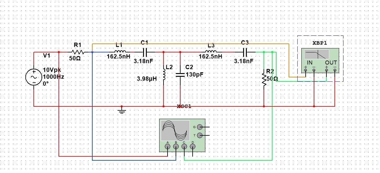
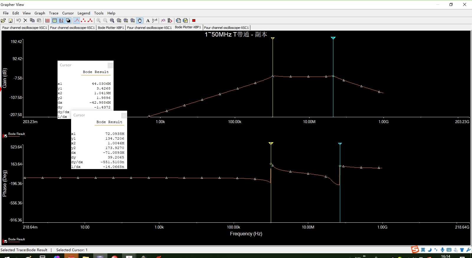
customer designed one Passive Bandpass Filter as follow picture shows,bandwith: 1-50Mhz, and another piecture show the simulate result with this design, the real test result with PCBA is almost the same with the simulation, but still we have one problem:
there is different phase shift with different frequency with in bandpass bandwith,
for example, if no phase shift with 5MHZ,
then, will shift ahead with 1Mhz and shift behind with 20MHZ,
so, the output signal will distort if input frequency changed from 1MHZ to 20MHZ in this case,
customer need help to advise any solution to solve this problem,
the valid bandwith is 1MHZ-30MHZ in customer's design,
thanks.
b/r
vincent