This thread has been locked.

If you have a related question, please click the "Ask a related question" button in the top right corner. The newly created question will be automatically linked to this question.

LMH6559: Typical Schematic

Part Number: LMH6559

Hi all,I use LMH6559  to assure that the excitation signals have low impedance

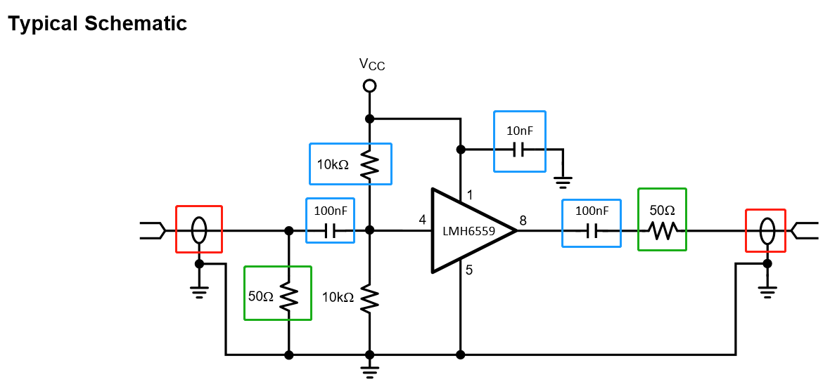
And I have some questions about LMH6559 Typical Schematic

1.What does the oval marked by the red box mean?

2.In AC circuit, it is necessary to have the components marked by blue box ?

3.The figure 1 below shows that the test circuit load is 50. In other values of the load, does the value of the resistance component marked by the green box of the circuit need to be changed?

  • Hi user5994204,

    The loops in your red boxes represent grounded coaxial cables, which will be required for transmission of high frequency signals to and from the amplifier.

    The capacitor at the input isolates your input signal's DC bias from the ideal, mid-supply dc bias for the amplifier. the two 10k resistors set that DC bias without loading the supplies or AC signal. The capacitor at the output provides the same function for the output, preventing any heavy DC loads from reducing the frequency response. The 10nF capacitor is needed to supply short bursts of power to the part without passing through the inductance of the power pcb wires.

    The 50 ohm termination at the amplifier's input and the 50 ohm source impedance at the amplifier's output are for transmission line impedance matching. They will need to be different if you use a transmission lines with a different characteristic impedance.

    Best regards,

    Sean