This thread has been locked.

If you have a related question, please click the "Ask a related question" button in the top right corner. The newly created question will be automatically linked to this question.

LMH6559: LMH6559 Schematic

Part Number: LMH6559

Thanks a lot to Sean for answering the last question about LMH6559 typical schematic.But I still have some questions.

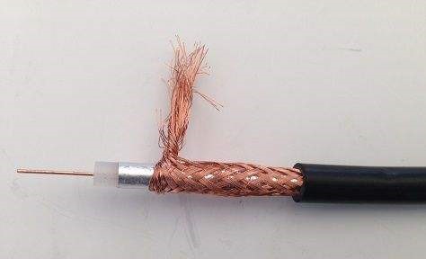
1.How does the coaxial cable connect to the conductor at the cross 1、 2、 3 with the red mark?   Is it to strip the insulation cover off a coaxial cable and expose the copper conductor, connect the copper conductor of coaxial cable and conventional wire?

2.Where does the VEE come in? Is it just that enter directly from pin 5 without going through other components or conductors?

                                       coaxial cable

  • 1. Typically, the coaxial cable has a SMA connector at the end which you screw onto a pcb mounted connector. The sheilding is then electrically connected to the ground plane of the board. The internal signal trace of the coaxial wire goes through a PCB trace to the amplifier.

    2. In this case, Vee is ground. It can be connected to the nearest available ground plane.

  • Thank you ,your answer is very clear !

    But about the second point,I still confused.

    If the signal passed is positive and negative (±5V), VEE should be connected to -5V ~ -6V, then this circuit structure is still applicable? If not, the improved way is to connect pin 5 to the power supply without connecting to the ground?

    Best Regard

  • Yes, for a +-5V signal, you should connect Vee to -6V instead of to ground.