This thread has been locked.

If you have a related question, please click the "Ask a related question" button in the top right corner. The newly created question will be automatically linked to this question.

OPA2180: Rogowski coil signal acquisition

Part Number: OPA2180
Other Parts Discussed in Thread: TIDA-00777, OPA2188, TPS65131, OPA2197

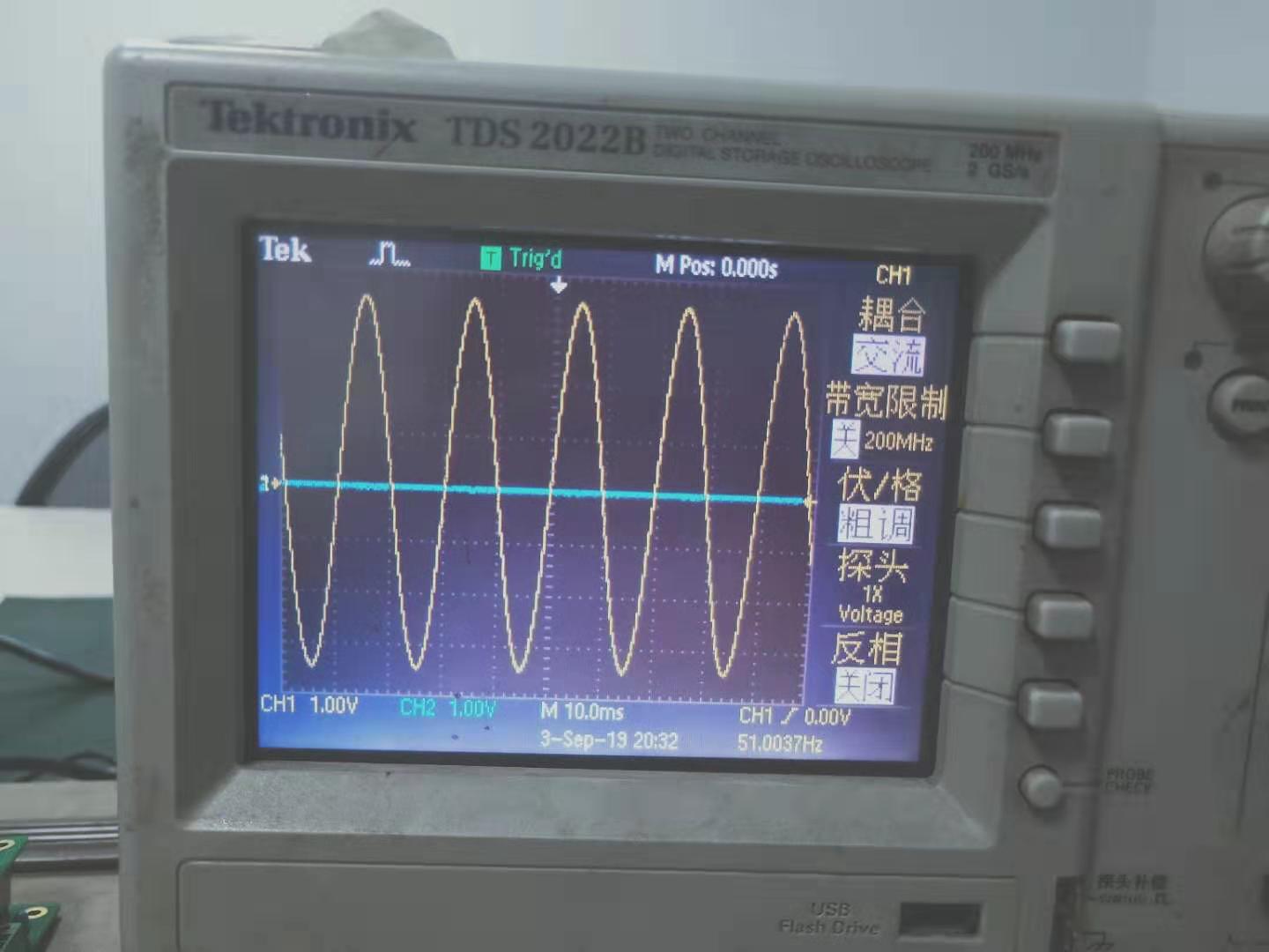
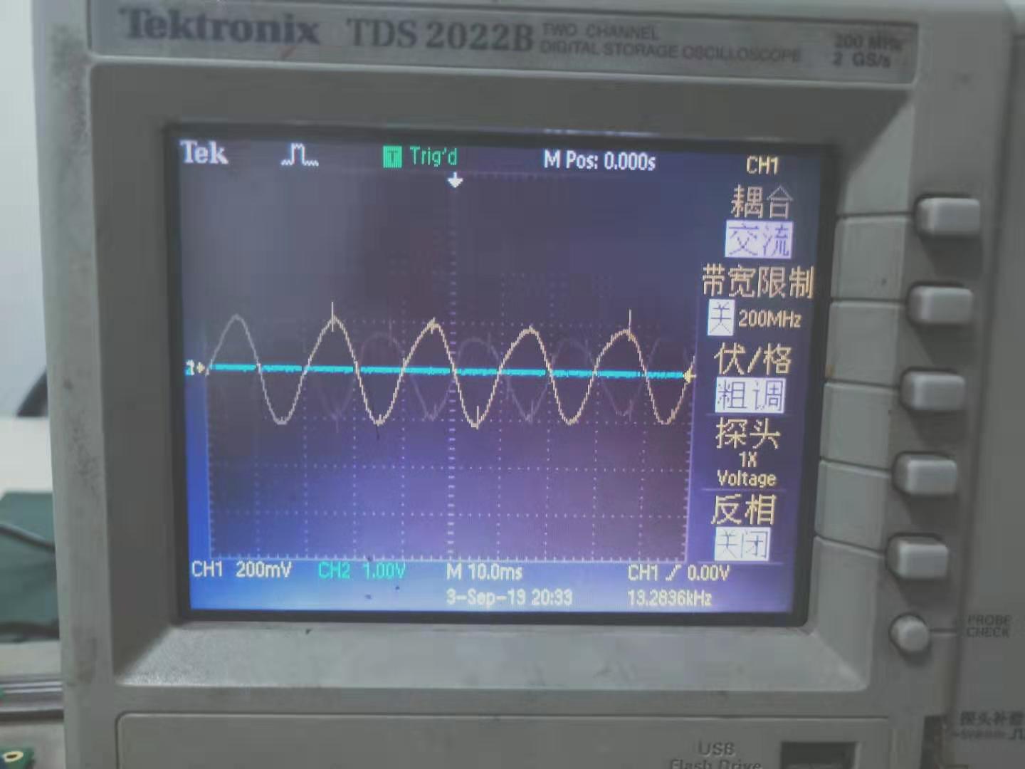
1、I use a signal generator to generate 50MV, 50HZ signal to the J2 input terminal of TIDA-00777.When I connect the positive signal to the PIN of J2 and the negative terminal to PIN2, the output signal is the correct amplification factor, but when I reverse the connection, the output signal is wrong, the signal is very small.Assume that the magnification is about 70 times。The first picture is the output waveform of the positive connection, and the second picture is the output waveform of the reverse connection. Why?

2、How large is the normal operating current of the OPA2188? I now use the TPS65131 which output ±15V to power 7channel OPA2188s, and I feel that the output current is not enough.

  • Hello user4973896,

    1. I would really need to see your complete circuit design, and the connection of the Rigowski coil to determine why the gain is different when you reverse the coil. Please show the loads used in your circuit.
    2. The OPA2188 operating current is listed as 485 uA maximum per amplifier, at TA = 25°C. Seven devices, 14 channels total, would have a maximum operating current of 6.65 mA. The TPS65131 is capable of approximately +/-200 mA output current. Even if seven channels (not 7 devices) of OPA2188 devices are sinking/sourcing an output current of +/-10 mA, the total operating plus load current would be under 100 mA - well below the TPS65131 maximum output current.

    Regards, Thomas

    Precision Amplifiers Applications Engineering 

  • When i test, I short pin1 and pin2  of  JP4, pin1 and pin2  of   JP5.The output signal AIN2 and AIN2GND is  connected  directly  to  ADS8588SE whose range  is  ±10V.

  • Hello user4973896,

    I do not find any reason why the output level from the OPA2197 amplifier and integrator stages would produce less output voltage when the Rogowski coil is reversed, at least not due to something they are doing differently. About the only explanation for the different amplifier/integrator output levels would be if the Rogowski coil is producing a different output for the normal and reverse connections.

    Can you observe the output of the Rogowski coil, or input to the first OPA2197 input stage with a DSO, as the coil is connected using the normal and reversed connections? If you can't observe the coil output directly, then see what you get at the output of the first amplifier stage.

    Regards, Thomas

    Precision Amplifiers Applications Engineering

  • Hello, 

    We hope your issue is resolved. I am going to close this thread now. Feel free to reply to to re-open if you have any questions moving forward.

    -Tamara