This thread has been locked.

If you have a related question, please click the "Ask a related question" button in the top right corner. The newly created question will be automatically linked to this question.

OPA171-Q1: Could you please help to understand the circuit

Part Number: OPA171-Q1
Other Parts Discussed in Thread: OPA404, OPA171

Hello All,

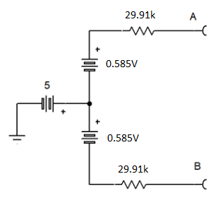
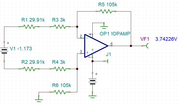
I have given a circuit as below and simulated in P-Spice. I am confused of the circuit working behavior.

1. Could anyone help to understand the circuit behavior and the impact of 5V at R5 and R6 node.

2. also explain solved solutions for the voltages displayed in simulation result. 

Thanks in advance.

Sathish Kaliappan

  • Hello Sathish,

    From R7/R8 to output is a standard differential amplifier circuit and I won't cover that here.

    The rest of the input circuit looks like this.

    The resistors to the 5V supply create a 5V common mode. In an unloaded state with 400V on, both inputs are positive. This was likely the goal of the design values. The difference gain is 60k / (60K + 2.4M) = 1/41. The output impedance of AtoB is 60k || 2.4M = 58.54k 

    So the circuit also works like this. The resistors add up to 58.54k, the common mode is 5V. The 400V supply is divided by 41 and split in half to become balanced

    Lastly the resistors here add to the 3k resistor in the diff amp to calculate the diff amps gain.  

  •  Dear Ron,

    Thanks for your response.

    Actually the value of R1 and R2 (in your circuit) is 10.2MEG in my case.

    If consider this and go with your calculation , The difference gain is 60k / (60K + 20.4M) = 1/341. The output impedance of AtoB is 60k || 20.4M = 59.82k 

    and if I divide 400V by 341 --> 400/341= 1.173V

    But if I refer to this value as per your representation, my simulation result is not matching.  Please have a look.

    Thanks

    Sathish K

  • Sathish,

    with 10M (not 1M), I agree with the 341:1 divider and 59.82k impedance (29.91k per side) 

    The gain of the op amp diff amp is Rf / Ri = 105k / (3k + 29.91k) = 3.19 V/V

    Putting it all together 400V * 1/341 * 3.19 = 3.742V; that is close to 3.671 (71mV difference)

    The op amp offset error could be a cause. The 'noise gain' of the circuit is 1+ Rf/Ri  so it is 1 higher than signal gain.

    However, 71mV / 4.19 is 17mV and the op amps inputs measure the same in a mili-voltage resolution, so offset is not the answer.

    I simulated my "equivalent circuit and got 3.742V so my math works out.

  • Sathish,

    The results will match yours, when 103k resistors replace the 105k resistors. Diff amp gain changes to 3.130 for output 3.671V

  • Sathish,

    Lastly, I want to stress that the 30k resistors need to match each other well. A 1% error gives a 25mV output shift.

  • Dear Ron,

    Thanks for your support. Your math works great and matches exactly.

    And I have a question regarding open condition or 0V instead of 400V. So I expect 5V will be the major source to the op-amp inputs

    expectation is 0V at OP-amp output (if am correct), but I get 0.412V (OPA1013) and 0.542 (OPA404)

    also am NOT seeing same voltage potential at V+ and V-

    Does it due to some offset issue with simulation models? or any other factors?

    Correct me if am wrong.

    Thanks,

    Sathish K

  • Sathish,

    The 0V input state should produce a theoretical zero output. The "negative" power source for the op amp is also zero. No op amp produces an output range that fully swings from V- to V+ (power supplies). The model can reflect that in a few ways, the right way (for drain output structures) would to simulate a fixed series resistance. However some op amp models just use a fixed voltage. 

    To test this, connect the V- pin (pin 4) of the op amp to -1V and check the output again. If the output is much closer to zero, then that was the issue. Check the data sheets to see how low VOL can be while sinking about 40uA needed.

  • With OPA171 simulation, 30mV output with op amp V- at 0V and 1mV with V- at -1V

  • Dear Ron,

    I understood . Thanks and I appreciate your great support.

    Expecting the same in future :)

    Thanks,

    Sathish K