This thread has been locked.

If you have a related question, please click the "Ask a related question" button in the top right corner. The newly created question will be automatically linked to this question.

LM324: Possible causes for active filter showing slow roll-off

Part Number: LM324
Other Parts Discussed in Thread: OPA4251, OPA330

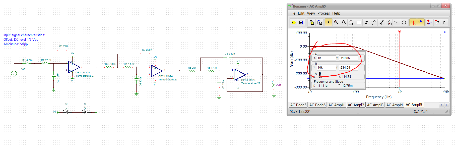
I have frequently used the LM324 to design Op-amp circuits. Just recently I stumbled upon a rather enigmatic problem for me. I'm designing a 6th Order, 100Hz low-pass, Non-inverting, unity gain, Sallen-Key Butterworth filter with an LM324 Op-amp at its core. The problem is that, when testing, instead of the expected 120dB/dec Roll-Off for a 6th Order filter, I am getting a 90-100dB/dec Roll-Off (Equivalent to a 5th Order Filter). I am using capacitors in the range of 22nF to 1uF with 5% tolerance and resistors in the range of 1KOhms and 30KOhms with 1% tolerance. When inputting design data of the filter parameters to WEBENCH: Filter Design Tool, turns out that there are also capacitors on the nF to the uF range.

After browsing in the forum, looking for some information and related issues, I found a similar problem but with the OPA330. There it was suggested that high resistances were most likely altering the filter's response. I also found, by browsing through the web, information regarding to the Q factor, filter coefficients, gain, cut frequency and GBW relationship. So far I have determined I need a 20KHz GBW Op-Amp.

What has come to my attention however is the fact that, in the LM324 datasheet, there is a note regarding to capacitive load driving capability of the IC which is limited to 50pF, which is gain dependant. This note does not exist in the OPA330, however a figure is provided showing the overshoot vs the load capacitance. Adittionally, from LM324 datasheet in the voltage follower pulse response figure, it is shown that the Op-amp can achive a 0.25 V/uS Slew Rate whereas the OPA330 has a 0.16V/uS and the OPA4251, recommended by the  WEBENCH: Filter Design Tool, has a Slew Rate of 0.01V/uS and a GBW of 35KHz, instead, the LM324 has a 1MHz GBW.

In essence, everything boils down to the following questions:

  1. I assuming the LM324 is an apropriate yet oversized core element for the filter I am bulding, am I right asumming such thing?
  2. Does the capacitive driving capability of the LM324 has something to do with slower roll-off in active filtering?
  3. Given a certain Op-Amp, is the maximum allowed capacitor value limited to the device's capacitive load driving capabilities? if not, which is the recommended capacitance value range to use in an active filter with a given Op-Amp and/or how to determine it?
  4. Can the Slew Rate degrade the filter response (make the roll-off band look like a 5th order filter instead of a 6th one, I am pretty certain it is the opposite)?
  5. What are other possible causes that may slow the roll-off speed of the filter (getting a 5th order roll-off instead of a 6th one)?
  6. Can capacitor dielectric material affect roll-off speed?
  7. Is an Op-Amp model swap recommended?, Which would be the characteristics to look for?, Are there any Op-Amps tailored for filtering?
  8. Are there any hidden issues/considerations with using the non-inverting configuration that I have missed?

I'd like to thank you beforehand for taking the time to look at this issue, I may as well suggest to include a component value modification feature (for capacitors) in the WEBENCH Filter Design tool. 

  • Hello Dario,

    There is an application note for the LM324 that is useful event for those that have used the LM324 many times. 
    https://www.ti.com/lit/pdf/sloa277

    Are your Sallen-Key Butterworth filters low pass, high pass or band pass?  

    I suggest starting by eliminating the time delay effect when the output current changes direction. Try add adding a resistor from output to ground (or negative supply if dual supply). Chose a value that gives a few milli-amperes of current flow.  If that doesn't fix the roll over rate, then something else must be the reason.

    Can you post a schematic, preferably in TI-Tina format.

  • we are guessing low pass?

    What shape, butterworth or what, zero ohm source?, what load

  • Hello Ronald

    Thank you for the info, I gave the application note a quick read and found some intresting recommendations for using the LM324. I will add some resistors, as you pointed out, re-test and post the results.

    Ron Michallick said:
    Are your Sallen-Key Butterworth filters low pass, high pass or band pass?  

    Right, I forgot to tell in the description. It is a Low-Pass Filter, I'll edit the problem description.

    Ron Michallick said:
    Can you post a schematic, preferably in TI-Tina format.

    I've just downloaded the tool, it will take me some time. Let me try eliminating the time delay as you said

    Thank you for your suggestions.

    Sincerely,

    Dario Martinez

  • Well this design does not need much GBP to implement - again, what shape? Using the older Filterpro tool for a Butterworth target (what the webench version uses) shows this. 

    Pretty low GBP requirements - if you are not getting the expected rolloff - 

    1. That is a pretty low signal level in the 60dB rolloff region, might have some measurement issues, 

    2. The SKF always has a stopband rejection issue as the LG rolls off, with the 1MHz LM324, likely not the issue

    3. Might have some feedthru making it look like the gain is not rolling off fast enough - don't take much at the -80dB level. 

  • Hello, Michael

    I'm curious about the term "shape". The shape is a low-pass filter of the butterworth type in a non-inverting Sallen-Key architecture, driven by a low impedance source (50 Ohm) and each stage sources a maximum of 5mA is that what you mean by shape?.

    By the way, the filter's input is always positive that is, input signal is DC biased. Could that be the issue with the filter? However I'm not so sure that could be the problem since capacitors in steady state are, ideally, like open circuits. Unless of course, capacitor's leakage current is high, in wich case leads me to the question, What kind (material) of capacitors are best suited for signal filtering?

    Also, it caughts my eye seeing equal resistors in the arrangement you show in the schematic, is there a special reason behind choosing equal valued resistors?

    Greetings

    Dario Martinez

  • Hello Ron,

    I've added the suggested resistors as you pointed out draining a maximum of 5mA, however, response is still the same. So the issue shoud be a completely different thing. 

    Thank you for the suggestion! I completely missed loading the amps a bit

  • Well there are an infinite number of pole combinations in a 6th order. Maximally flat is Butterworth. But there are lots more (bessel is linear phase, chebychev is sharper rolloff with passband ripple, etc. )

    Are you AC coupled? what is setting your DC operating point then? Can you show full circuit with values, preferably in TINA sim

  • Hello Ron, Michael

    Here's the schemtic in TINA format  6354.TINA_ANTIALIASING.TSC .As you can see from the schematic the input signal is not AC coupled as you can see. So essentially, my doubts are now:

    1. Does capacitance driving capailities of the Op-Amp degrades filter perfomance?
    2. The properties of the dielectric material of the capacitors can degrade filter perfomance?
    3. Which capacitors less hinder filter performance?
    4. Is DC bias degrading filter response?

  • Dario,

    How are you determining the role off rate? What frequencies were used? What equipment was used? Which LM324 amplifiers were used for each stage?

    When amplitude differences are more than 80 to 100dB other factors come into play such a ground imperfections (different ground nodes not being exactly the same), trace to trace board parasitics. 

    Swapping out the op amp is a simple way to see how much it plays a role. The datasheet for LM324 say typical cross talk separation is 120dB; that doesn't include external crosstalk paths.

    1) The op amp doesn't drive any direct capacitance.
    2/3) I have no experience with that topic.
    4) The DC bias looks OK.

  • Dario,

    Can you try measuring the roll off for each stage separately; [IN to AMP1 OUT]  [AMP1 OUT to AMP2 OUT]  [AMP2 OUT to AMP3 OUT]. Then add the gains together.

  • Well if I run this AC small signal from 1kHz to 10kHz it is more than 60dB/dec rolloff - what was the issue again? 

  • Oops, for a 6th order we are looking for more than 60dB/dec. More like 120dB/dec. 

    If I run an ideal 6th order 100Hz butterworth SKF LP in Filter pro, I get this curve - pretty much matches the TINA sim - I don't thing there is a problem in sim, is the problem on the bench? at 1kHz the ideal response is 120dB down, just like the TINA sim. Above 1kHz, that is getting into measurement and xtalk issues. 

  • Hello, Ron

    I am measuring the magnitude via the FFT function of the oscilloscope, with a Hamming Windowing, as it returns dB as the result. I make then a manual sweep from 10Hz to 350Hz and write down the magnitude read from the oscilloscope.

    It is worth pointing out that, I chose to stop the sweep at 350Hz because at that point attenuation is around -48dB and nearing the noise floor of the oscilloscope. So worries about measuring at -80dB or -100dB. Afterwards, I plot the obtained data in an semilog plot and analize the steepness of the Roll-Off section of the filter. The maximum steepness I've found is 100dB/Dec. I might try to switch the Op-Amp but I'll have my search restricted to DIP packages as I'm using DIP carriers.

    I may as well try looking at each section seaparately and plotting the results individually. I'll post the results in more or less 3 days as I'm going to be a little busy

    Regards

    Dario Martinez

  • Hello, Michael

    Yes it is a physical circuit, simulations in TINA give the aprorpiate response, however it is not what I'm getting out of the phyisical implementation of the filter.

  • Dario,

    Thanks for explaining your setup. It helps a lot. "FFT function of the oscilloscope, with a Hamming Windowing" does a lot of processing so I don't fully trust that for a single frequency evaluation. DIP carriers suggest a setup that is not a professional and dedicated printed circuit board layout. So unintentional cross talk could be a factor, if this factor was dominant I would expect phase shift to be close to 0 degrees or 180 degrees (and stop shifting with frequency).

    In any case here is the steady state 350Hz Tina result. I suggest using real time amplitude scope mode. 

    This should be (per AC transfer result) -65dB -470 phase lag. 

    Less than 3mVpp is real time waveform expected. To read that you could use a active differential probe and uses a high number of averages to squash the noise. Differential probe is needed as any ground difference from a regular probe could introduce errors. Harder would be to add a local preamplifier amplifier. 

  • Hello Ron, Michael

    I finally got some free time to resume testing the filter. I went to test stage by stage as Ron suggested but, this time on LTspice. I reviewed once again all the design procedure and input the values in case I have had missed something and, I got what all the simulations said so far "It should work". So I went on to test the components to try and feed the simulation with the real values of the implemented circuit and, this time to my surprise, I was able to determine the cause of the malfunction. I had placed a wrong resistor value in one of the six stages of the filter. I fed the simulation with the wrong component and the slow roll-off issue was correctly simulated.

    Then, should the question of "What could be the causes for a filter to show a slow roll-off behaviour?" arise again "Check your values thoroughly!" should be the answer.

    In the figure you can see the Slow behaviour of the filter due to a wrong component value in Red, and the correct behaviour of the filter in Cyan.

    Thank you guys for yout time and support, this issue got my head scratching a little bit. 

  • Dario,

    I am glad you solved the dilemma and told the story. Sometimes, I forget to start over when things just don't add up.

    It only seems obvious once the answer is known.