Hi,
Datasheet page 1 shows that minimum trans-impedance gain of OPA657 is 66dB. Can we achieve trans-impedance gain 50dB or lesser?
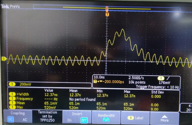
We observed some oscillation in output with low gain.
![]()
regards
Vinod Sharma
Original question:

Hi,
Datasheet page 1 shows that minimum trans-impedance gain of OPA657 is 66dB. Can we achieve trans-impedance gain 50dB or lesser?
We observed some oscillation in output with low gain.
![]()
regards
Vinod Sharma