This thread has been locked.

If you have a related question, please click the "Ask a related question" button in the top right corner. The newly created question will be automatically linked to this question.

AMC1302: AMC1302 Output distortion

Part Number: AMC1302

Hello,

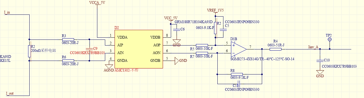
My customer has been using AMC1302 for current sensing. They have found AMC1302 output distortion when input is 20KHz, +/-40mV voltage signal. The gain of AMC1302 is 41. However, with the same schematic and parameter, the input signal decrease to 550Hz, we no longer see the distortion.

Could you explain what possibly cause the distortion?

This the schematic:

This is the input& output waveform:

Thanks!

Paul

  • Hi Paul,

    AIN should be reference to GNDA, which I do not see here. Is AIN referenced to GNDA somewhere not shown in the schematic?

    There may be a violation of the input common-mode. 

    Can you confirm exactly where these signals are being measured? 

    Is the "input signal" measured at the device pins or across the shunt resistor? 

    Is the "output signal" at the device pins or TP2?

  • Hi Alex,

    Yes, AIN and GNDA is connected somewhere.

    The input signal comes from a current probe and output waveform has been capture from PIN6~PIN7.

    Currently, we found the there is large ripple on Vdd1 and suspected the ripple degraded AMC1302 performance. Experiments are running to verify it.

    BTW, 20KHz signal frequency should lead to such distortion. Is that right?

    Thanks!

    BR

    Paul  

  • Hi Paul,

    Thanks for the additional information. I imagine that the current probe is connected across the C9 cap?

    A large ripple on the power supply could certainly be the reason. An LDO or regulator may be necessary to clean up the signal. Our EVM can be used as an example schematic for this. 

    There should not be an issue with 20kHz input signal frequency. The bandwidth of this device is 280kHz.