This thread has been locked.

If you have a related question, please click the "Ask a related question" button in the top right corner. The newly created question will be automatically linked to this question.

OPA4872: 10:1 multiplexer

Part Number: OPA4872
Other Parts Discussed in Thread: OPA4172, OPA695,

Dear Sir/Madam,

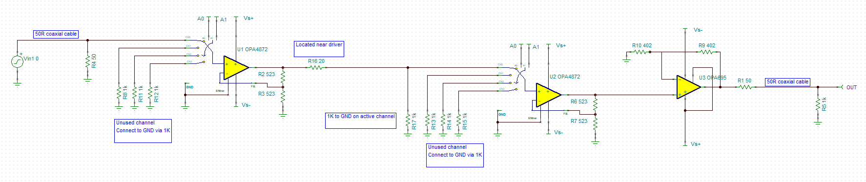
I need a 10:1 mux that supports from 0Hz to 200MHz.
I am wondering if it is a good idea to cascade as shown below and whether I need an additional op amp to drive a 50R coaxial cable?
Any thoughts or suggestions are welcome.

Regards Joe

  • Hello Joe,

    You can use the method highlighted in Figure 31 of the datasheet. Note the for table 3 Ro would have different values since you are using a 50-ohm line instead so be sure to adjust the calculations accordingly.

    Best,

    Hasan Babiker

  • Figure 31 is doing an 8 to 1 using a wired or mux to combine the two output stages. I think you want 2 layers of OPA4172 so the outputs of the 10 layer one would feed into a 2nd layer of OPA4172 -

    you do not need to take interstage termination losses just run a series 20 ohm to say a 1kohm to ground at each input of the 2nd layer (need DC bias current paths for inactive channels) and terminate the unused inputs with 1kohm as well to gnd on each one, 

  • Hi Michael,

    Thank you for the reply. Two stage is what I am after. To summarize:

    1K pulldown resistor on unused analog inputs.

    20R resistor located near driver and 1K pulldown on active inputs of the second stage.

    I have added OPA695 to the output to drive 50R coaxial cable and provide additional gain.

    Do you see an issue with this arrangement?

    Regards Joe

  • Morning Joe, 

    That sounds right, 

    1st layer, you have 10 inputs, they will 3 parallel OPA4872's where two channels will just have 1kohm to gnd unused,, 

    You would terminate those 10 inputs in what your sources needs to see

    Assuming tight layout, the interstage to the next layer of 3 to 1  is where the series 20ohm (to isolate next stage C) and 1kohm to ground are used, with 1 channel not used and just terminaed to gnd with 1kohm 

  • Hi Michael,

    Thank you. Is there any benefit to use similar 20R and 1K on the input of the OPA695?

    Regards Joe

  • Well Joe, the idea with the shunt R is to make sure the source is never open to the input circuit. Going from that last OPA4872 output to the OPA695 (if a tight layout) could use the series 20ohm to isolate the C input, and, maybe on power up it might not hurt to have that 10k to ground - but unless you are disabling the OPA4872 output stage, that source should not open up. 

    So, I would put a place for the shunt R and see if you need to populate it. 

  • Hi Michael,

    Thank you. 

    Regards Joe