This thread has been locked.

If you have a related question, please click the "Ask a related question" button in the top right corner. The newly created question will be automatically linked to this question.

LM331: It does not work properly)

Part Number: LM331

Have A Nice Day! It was necessary to assemble a training model in College: frequency-voltage, voltage-frequency. From the most affordable chips I chose LM331, chose the simplest schemes from the Datasheet, assembled the printed circuit boards, checked the wiring of the elements 10 times, everything is correct in my opinion. Until that tested on chips production HGSEMI, but think that need to buy the original of the from TI or National.
FVC.
VCC = 15-17V.
Fin = 100 Hz to 11 kHz.
All items are set as in the Datasheet.
Input rectangular pulse 50%, 3Vpp (less than 3V at the input of the LM does not react)
Initially, everything worked fine, removed a good characteristic (1kHz ~ 874mV, 10kHz ~ 8.75 V etc).
Suddenly, at some point, the chip stopped working, the output is 11.3 V, there is no reaction at the input. We didn't even know what happened. There is no "saw" on this chain. 5 the output of the chip is 400 Ohms relative to the ground. I assume that the input has broken through? Why did this happen? What is the maximum signal amplitude to be at the LM input? Is it necessary to shift the input pulse towards the negative voltage? May need some protection at the input? I really need help.) Inserted into the panel another such new chip, again reached 10kHz, did not notice, and the output is again constant 11V.... The same thing…
VFC.
VCC = 15-17V
Input voltage = 0-10V
All items are set as in the Datasheet.
According to the Datasheet promise that the output will change the frequency from 0 to 10kHz depending on the supplied voltage, in fact it seems to work, but not quite as I would like, the maximum frequency which could achieve is 700 Hz at the average position of the engine (about 5V), with a further increase in the input voltage, the frequency begins to decrease in the same sequence, although it should grow, it turned out about this characteristic:

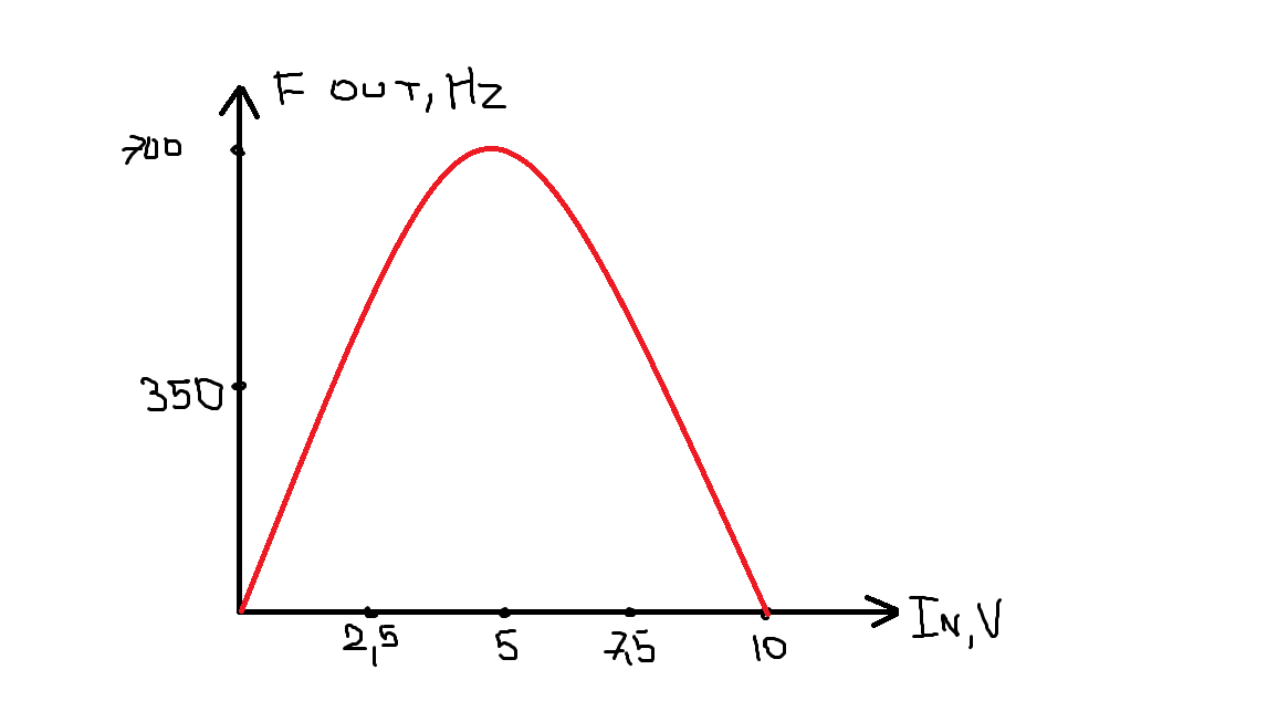
I can't understand why it happened. What is it connected with? All the elements checked several times, but still does not work correctly, could it be due to the fact that the chips are manufactured by HGSEMI? Photos from the oscillator and oscilloscope unfortunately applying can't, because I forgot to take a picture. Thank you all for your help.

Photos.rar

  • Hi Anton,

    TI has no insight into the quality or reliability of the HGSEMI LM331 device you have been evaluating. You mention "Suddenly, at some point, the chip stopped working, the output is 11.3 V, there is no reaction at the input. We didn't even know what happened. There is no "saw" on this chain. 5 the output of the chip is 400 Ohms relative to the ground. I assume that the input has broken through? Why did this happen?" It does sound like the device is now defective, or was damaged in handling or test.

    I suggest you do obtain a TI LM331 device and test it in your V-to-F and F-to-V circuits. Be careful to observe good ESD handling practices when handling the LM331, or any other semiconductor devices.

    You can check with the TI Authorized Semiconductor Distributors in your region and see if they can obtain couple of samples for you, or purchase some from them. Also, the TI store can sell orders as small as one unit for your project.

    Regards, Thomas

    Precision Amplifiers Applications Engineering

  • Thanks for the answer! If would was such opportunity buy the original of the from TI, then I would of course bought, but budget facilitated only on analogues from HGSEMI) AND if order samples, then there is necessary corporate mail, which I have as have student, unfortunately there is no. I will try to buy a chip from National SEMICONDUCTOR in a local store, check and unsubscribe about the results)

  • Hello Anton,

    Once you have the TI LM331 in the circuit do let us know if the performance is correct, or if you receive the same results as the HGSEMI LM331. Be sure to check your circuit and whatever you are connecting externally to make sure you are not setting up the LM331 for incorrect conditions, before powering the new device for the first time.

    Do note that much of the TI US operations will be at minimum staff during the Christmas and New Years holidays so responses on the e2e may be much delayed.

    Regards, Thomas

    Precision Amplifiers Applications Engineering