This thread has been locked.

If you have a related question, please click the "Ask a related question" button in the top right corner. The newly created question will be automatically linked to this question.

LMH6518: SPI operation mode

Part Number: LMH6518

Hi,

I have been working with the LMH6518 trying to design a AFE and currently i am facing difficulty while trying to make spi of the LMH6518 work.

I am using an xmega32d4 @ 3.3V.

I have worked with spi in the past but this case isn't that straightforward.

The xmega has MOSI & MISO while the DVGA has SDIO. I have arranged that through a 1K resistor as follows: (already asked here about that)

PC5 is the MOSI pin and PC6 is the MISO (receiving data from LMH6518)

The DS says that mode-1 should be used and gives a few drawings that explain that.

The xmega32 has mode-0 up to mode-3 which do not seem to work.

I tried off course mode-1 but the sample-data vs clk edge did not suit.

So i am thinking that mode-1 of the DS is not mode-1 of the xmega DS.

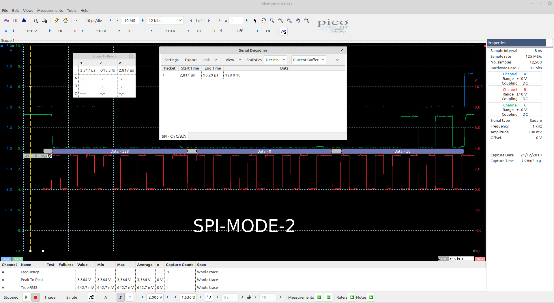
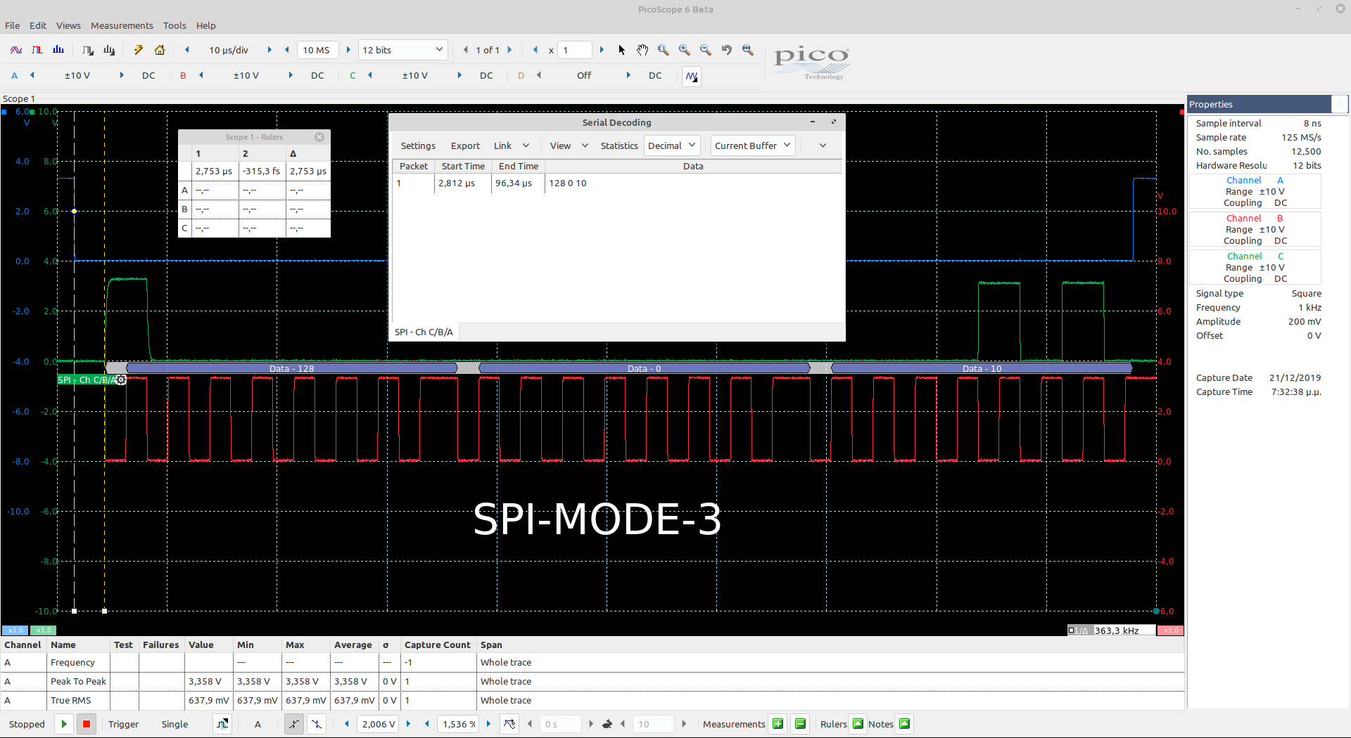
I moved on taking 2 screenshots with my scope while using modes 0 & 1 in order to detect pulses on the SDIO pin.

I was never able to detect pulses in any of the 4 spi modes of the xmega32.

Here are the screen shots:

I should be getting something on the SDIO but i do not.

I have checked soldering joints and power +3.3V on the LMH6518 and they are ok.

Its' quiescent current is also as suggested by the DS.

Regarding the code i am using i do the following:

1) Set CS low

2) Send 0b10000000 to set LMH6518 spi into read mode

3) Send a dummy byte 0 to get a byte corresponding to the previous 0b10000000 command

4) Send a dummy byte 0 to get another byte corresponding to the high byte of 16bits

5) Send a dummy byte 0 to get another byte corresponding to the low byte of 16bits

6) Set CS high

Is that correct?

What about programming the bits of the 16bits of the LMH6518?

Should i do the following:

1) Set CS low

2) Send a byte 0 to set LMH6518 spi into write mode

3) Send a byte to program the high byte of the 16bits

4) Send a byte to program the low byte of the 16bits

5) Set CS high

Can you pls help?

Regards

Manos Tsachalidis

  • Hello Manos,

         I know a couple weeks ago a colleague of mine recommended the 1kOhm resistor on the bidirectional pin. Just to make sure this is not the issue for your situation, would you be able to measure with SDIO connected to either MISO or MOSI, but not to both for separate situations (write and read command). If you are able to get the correct signal over the SPI bus, then I could recommend another solution for having full duplex capabilities. Also, is the CLK signal measured at SCLK which is being sourced by the microcontoller? For future plots, would you be able to decode the SPI bus signals for clarity?

    Thank you,

    Sima 

  • Hi Sima,

    Thanks for your message. First of all, if you you do not mind, i would like to confirm with you whether i am doing the right thing, as far as the code is concerned.

    Should i be sending the 0b10000000 and then dummy 3x0 bytes in order to get the response from the LMH6518?

    The pcb is already manufactured. Traces are like the schematic above suggests. However i could do some debugging since the uC & the LMH are on different pcbs connected via a pin header. I will see what i can do there and come back.

    You are probably referring to a tri-state buffer already mentioned in another post... I will separate the two pcbs and connect them via individual cables so that i can intervene to any of them while trying to find what is wrong.

    I could also try to decode with my scope the pulses.

    Can you pls confirm, first of all, whether i am doing the right thing as far as the commands i am sending are concerned?

    Thanks

    Manos

  • Hi Sima,

    Everything works fine.

    The reason it did not yesterday is the fact that i started with mode-1 and all day long i did not power recycle the LMH6518.

    I just came to retry and it just worked when i powered up!

    Modes 0 & 3 seem to work fine both on read and write operations.

    I have attached 3 scope screenshots with modes 0, 2 & 3. Mode 1 does not work at all which contradicts with the datasheet!

    The clock is set @ 250KHz.

    Thanks again for the support.

    Regards

    Manos

  • Hello Manos,

        Thank you for sharing the scope shots, I am glad it works! I did forget to mention that your code looks completely fine to me. I will keep your solution in mind if anyone else stumbles across this problem.

    Thank you,

    Sima