This thread has been locked.

If you have a related question, please click the "Ask a related question" button in the top right corner. The newly created question will be automatically linked to this question.

XTR300: IA input has high bias current (40~50uA) in Spice model

Part Number: XTR300

Hello,

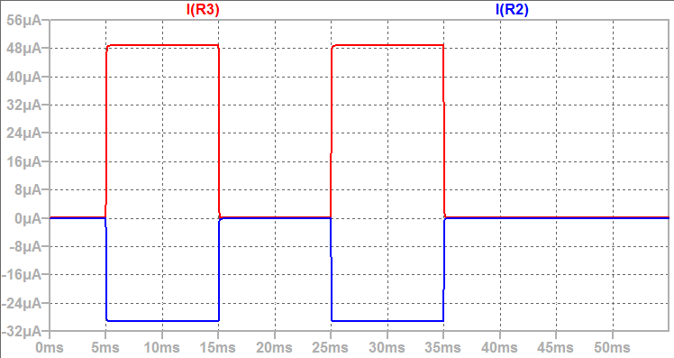
I have found a problem with XTR300 spice model. In my simulation with the spice model that downloaded from TI webside, the IA input is measured too high bias current in a range from 40uA to 50uA according to different resistance at input. The datasheet states the input bias should be less than +/-35nA. Could anyone have a look on this problem?

The other issue I'm trying to solve is too low slew rate in constant current mode while the load is in open state. I expect the voltage will ramp to the rail in a short time such as <1mS in typical slew rate. But the actual response is the output takes about 50mS to the rail. I realized this might be restricted by the low current from internal IMON current. In open load case or a high resistance load, the IMON is 1/10 of the load current which will be very low current in even nA or uA leven. The compensation capacitor in typical 47nF is too high to drive with so low current. I'm tying to solve this issue by external compensation loop with OPAMP. Anyway I hope this issue can be noted in datasheet descriptions.

Thanks,

Neil

  • Hi Neil,

    Thanks for your post. Please accept delayed response as many of us are on holiday break. We will support you shortly.

    -Tamara

  • HI Neil,

    The instrumentation amplifier of the XTR300 has an input bias current of 10nA as you have mentioned; however, the datasheet mentions that the the instrumentation amplifier has a typical input differential impedance of ~10^5 (~100-kOhm), and common-mode input impedance of 10^5 (100k-Ohm).  If the input voltage across the load is ~0-V, the current flowing into the inputs of the instrumentation amplifier is in the order of ~10nA; but if the differential input voltage at the IA input is 5-V (5-V across the load), the input current would be in the order of  ~50uA.

    On your second question regarding the slew rate, the typical slew rate in current output mode is expected to be around 1.3mA/us.  If possible please provide the complete schematic, and oscilloscope plots of the voltage at the XTR300 output and at the voltage input of the device.  Does the slow slew-rate issue occurs when load is present as well?   In your schematic, what is the supply voltage (V+/V-), the reference voltage, and the input voltage range generated by the DAC ?  Are you using pull-up resistors on the flag outputs of the device?  In addition to the compensation capacitor C2=1nF, is there any additional load capacitance?  Please also show the supply bypass capacitors and the circuit (or device) generating the voltage supplies on the schematic.

    Many Thanks and Regards,

    Luis

  • Hello Luis,

    Thank you for the helpful comments.

    That Slew rate question has been figured the problem with a 100nF capacitance as a filter at IA input. The team member provided wrong message when the such load capacitance was pointed out.

    Now the 100K input resistance you pointed is really a problem to consider in constant current applications where the IA inputs are connected to the load. In typical 4-20mA application, it's not a problem because the load is in series with the output. While user will have the IA input connected to the load for voltage measurement, just as the datasheet described the use case such as Figure 39. Standard Circuit Configuration), the 100K input resistance will impact the current accuracy. In other word, if IA is connected with load, the equation for current setting will be wrong if user doesn't take the IA input current into account. Your datasheet should describe this issue.

    Best regards,

    Neil

  • Hi Neil,

    It is good news that the slew rate issue has been resolved and Thank you for letting us know.  I also agree that the 100-kOhm differential input impedance on the instrumentation amplifier needs to be highlighted further or/clarified on the datasheet application section and will provide this feedback to the team.

    Thank you and Best Regards,

    Luis

  • Hi Luis,

    Checked with actual hardware to verify if there's really a 100Kohm resistance at IA inputs. The result shew it doesn't have high leakage current. Looks the real XTR300 chip doesn't have this low 100Kohm resistance. So you may want to check with your team if this is really the issue or it's Spice model related. 

    However, now I don't need to use the simulation to solve problem and the actual hardware doesn't have this high bias current either. In this case this feedback will be a question for you to consider if need to improve your datasheet or the Spice model for other users.

    Thanks for great support!

    Neil

  • HI Neil,

    I will verify/confirm this on the bench and look into updating the model; and look into updating the TINA model and correcting this discrepancy on the datasheet.

    I appreciate the feedback.

    Thank you and Regards,

    Luis