This thread has been locked.

If you have a related question, please click the "Ask a related question" button in the top right corner. The newly created question will be automatically linked to this question.

TL081: About the phase of signal in inverting and non-inverting

Part Number: TL081

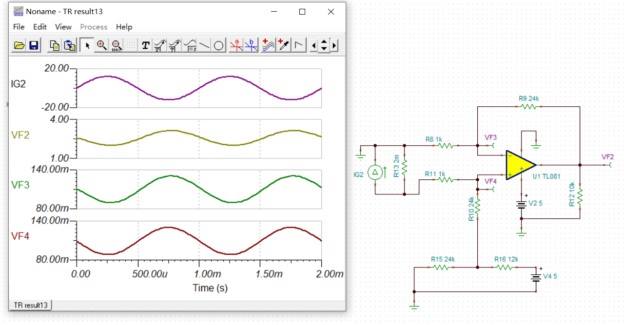
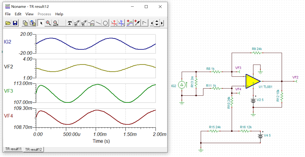
I simulate the current sensing circuit by TINA. When the signal is inverting input, I can see a 90 degree phase shift in IN+ and IN-. Why?

  • Hello User,

    At 1kHz, the dominant pole in the op amp will be active so the shift is 90 degrees and that is easy to see in the inverting case because the non inverting voltage isn't moving (<1mV). The same thing happens in the non inverting case however both pins are moving alot (common phase) so you can't see it.  

    Put a difference voltage meter across the input and you will see 90 degrees in both cases. Also notice that the output is the same in both cases, so it doesn't matter.